I promised to post details of how to use the telemetry options of openLRS with the FrSky Display screen and Telemetry Hub.
(John - I am not sure about converting C to Assembler because one reason to use C is that it stops it being specific to just one device. You may be able to do some conversion within the Microchip C compiler, but I haven't looked.)
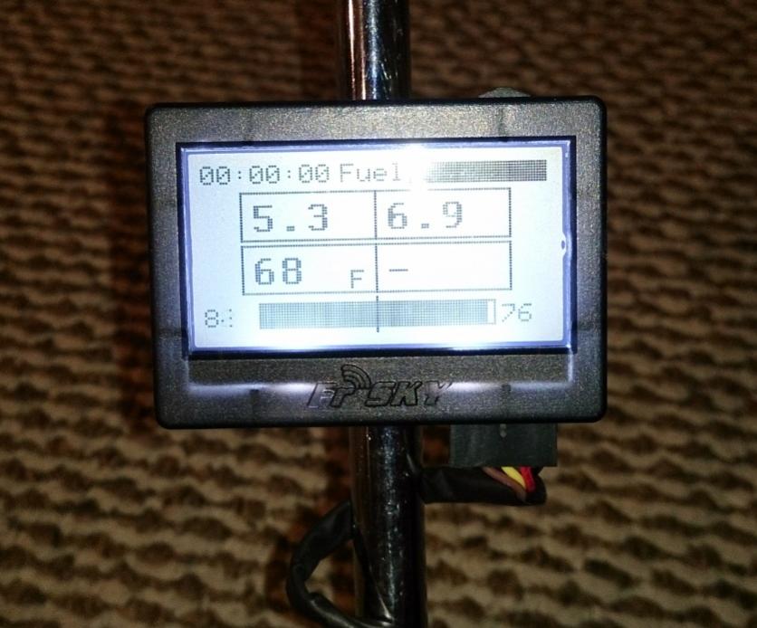
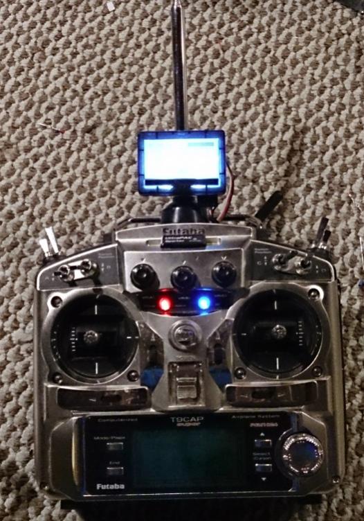
The display screen mounts on your transmitter and gives a wide set of options to give you data - most useful for aircraft, it has to be said.
The Telemetry hub goes at the receiver end and you can plug various sensors into it. It is designed to be used with an FrSky receiver but the clever openLRS community have included its use in their software.
First thing though is should you use the telemetry option?
Plus points:
- Signal strength data is very useful - it shows both the transmitter and receiver signal strength.
- Getting data back form the model sub is novel and could be useful e.g battery voltage for Lipos , or depth perhaps.
Minus points:
- I find the telemetry option gives servo jitter.
- The data hub and sensors contribute to the "cable jungle " in the close confines of model subs without adding that much to functionality. (I operate my subs more in "seat of pants" mode!)
Overall my conclusion is that I will only be using telemetry for setting aerials up or getting initial data from subs during development. For day to day sub operation I will just use the simple setup I outlined earlier in conjunction with a Walkie Talkie. The Walkie Talkie provides a useful signal strength indication and has potential for lost model detection. (I will always continue to use an audio Pinger.)
But here goes - the connection data for the telemetry modules:
First get your hardware. Copy of my order and what I paid at the time:
OrangeRx Open LRS 433MHz 9Ch Receiver 1 US$19.95 IN STOCK
FrSky FLD-02 Telemetry Display Screen 1 US$19.95 IN STOCK
OrangeRX Open LRS 433MHz Transmitter 100mW (compatible with Futaba radio) 1 US$19.99 IN STOCK
FrSky Battery Voltage Sensor - FrSky Telemetry System. 2 US$2.46 IN STOCK
FrSky FSH-01 Telemetry Sensor Hub 1 US$14.10 IN STOCK
FrSky TEMS-01 Telemetry Temperature Sensor 2 US$3.19 IN STOCK
You will also need to get out your soldering iron and get very few electronic components to assemble 2 simple little inverter circuits. One for the TX and one for the RX. Make it up in "dead bug" mode just soldering the component leads together as in the circuit diagram. The circuit diagram follows:
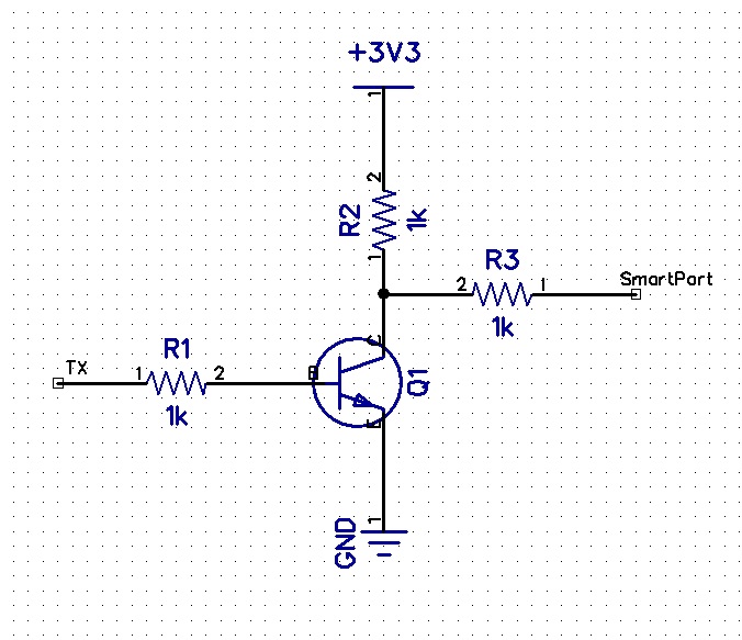
The diagram comes from the openLRS wiki (a very useful source of information:
https://github.com/openLRSng/openLRSngWiki/wiki
Tim S gives a lot of background on the telemetry, photos of the setup and the reason for needing the inverters on the SubPirates Forum.
You can use almost any small signal NPN transistor. (I used a BC548 because I had some handy.)
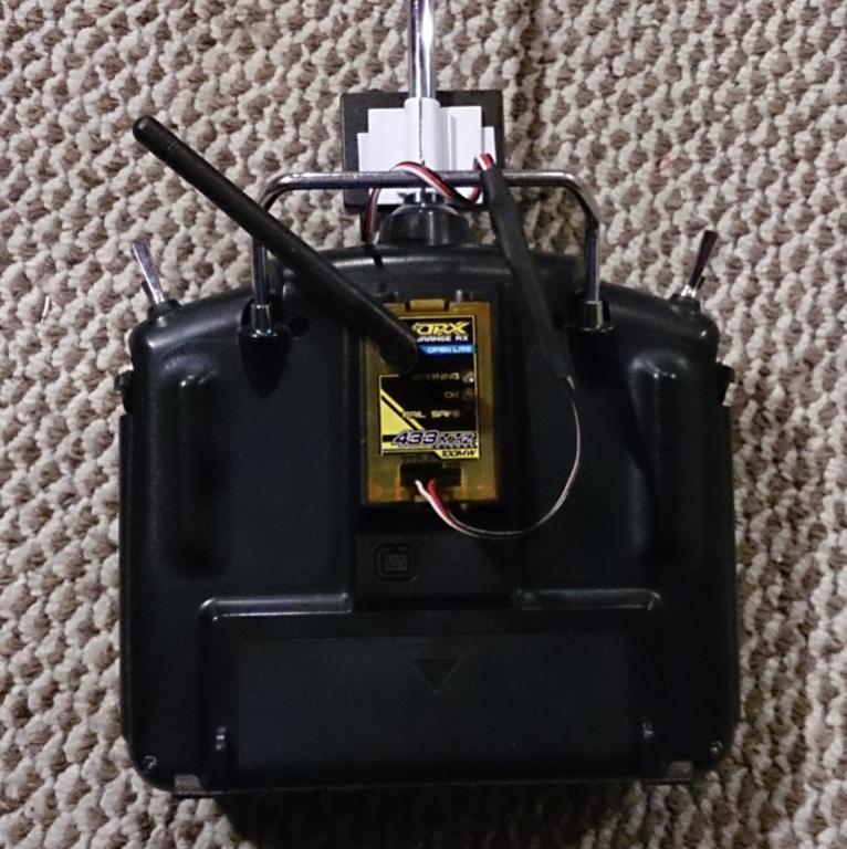
LCD Monitor on TXI will now describe how to connect up the data monitor on the TX to the openLRS TX module. I refer to the labels on the circuit diagram.
-Connect the TX pin on the Orange module (This is the 2nd pin from the left, next to the DTR pin) to the TX connection on the inverter.
-Connect the 3.3 v pin on the module (4th pin from the left ) to the +3v3 connection on the inverter.
-Connect the GND pin on the module (5th pin from the left) to the GND connection on the inverter.
- Connect the Smartport connection on the inverter to the TX pin on the Monitor. (2nd pin from Left)
- Connect +3v3 connection on inverter to +5v pin on monitor(3rd from Left)
- Connect GND connection on inverter to GND pin on monitor (4th from Left.)
Plug the module in, switch on the TX and the display should light up. Rotate and press the selector switch (opposite side to the plug pins) to go through the pages.
Sensor Hub at RXNext using the sensor hub. (You will need another inverter circuit.):
(In the latest edit I have included some later information from Tim S about battery voltage monitoring. Thanks Tim.)
The Hobbyking orange receiver connections are given here:
https://github.com/openLRSng/openLRSngWiki/wiki/Hardware-Guide
Connections to Orange RX pins next to the aerial. (DTR pin is next to aerial.)
- Connect GND pin (2nd pin from left) on the Orange RX to GND on the inverter.
-Connect 3.3v pin (3rd pin from left) on the Orange RX to +3v3 connection on the inverter.
- Connect RX pin on Orange RX (4th pin from left) (DTR is 6th pin from left) to SmartPort pin on inverter.
Connecting to sensor hub:
-Connect 2nd pin from the left on the Data connection of the Sensor Hub to TX connection on inverter.
- Connect 4th pin from the left (GND) on the Data Connection of the Sensor Module to GND on the invertor.
- Connect servo type cable from + - on sensor hub to any free servo connector on the RX.
Plug a sensor in (temperature is simplest) and you will see this come up on the LCD display. Hold the temperature sensor and you will see the temperature rise. Unless you are cold-blooded!
If you want to monitor battery voltage you will need a voltage divider network either home made or from FrSky. Connect the 0 to 3.3 voltage from this to either Port 10 (The SDA connection) or Port 11 (The SDL connection.) on the RX. (These connections are at the top LHS of the RX board. They don't have connectors fitted and so I soldered pins to Port 10 & 11 so that I could connect a trailing lead.)
The LCD display now gives you battery voltage. (Adjust the voltage divider in the LCD display software to get the right value.)
The next thing I intend to try is connecting an Orange TX module to any transmitter with a trainer plug. (I have a lot of old transmitters including ones for 35Mhz that could do with a new lease of life. I imagine you have too!)




» Futaba -868/915mhz equipment
» Darnell type 21 submarine, need some help
» Robbe Seawolf V2
» bladder bags
» WW2 mini sub build
» Peral Submarine of 1888
» U-Boat R/C?
» Cheap Arduino Auto leveler