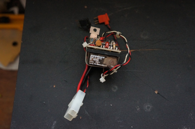
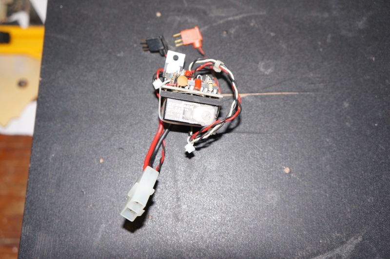
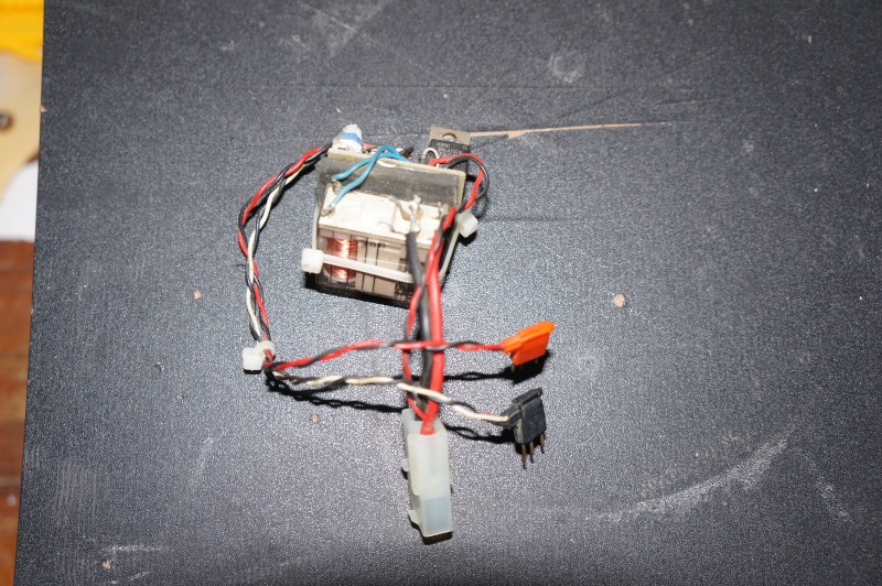
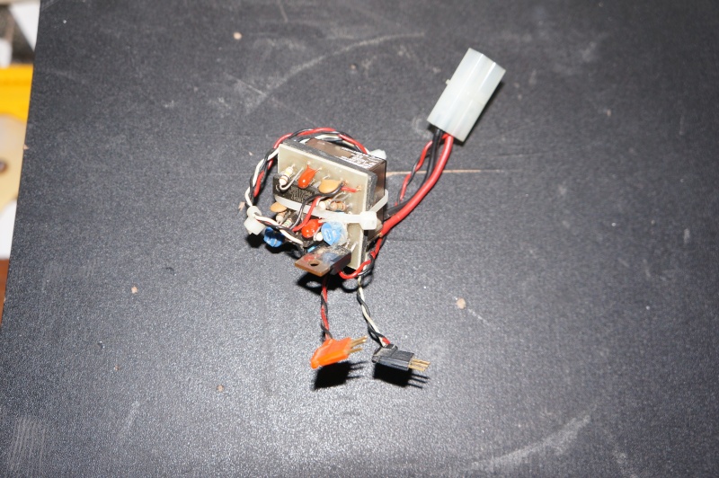
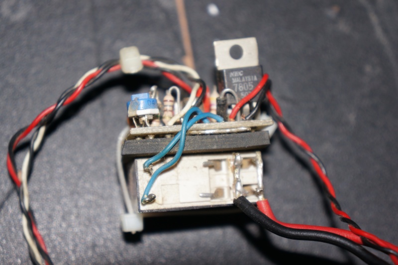
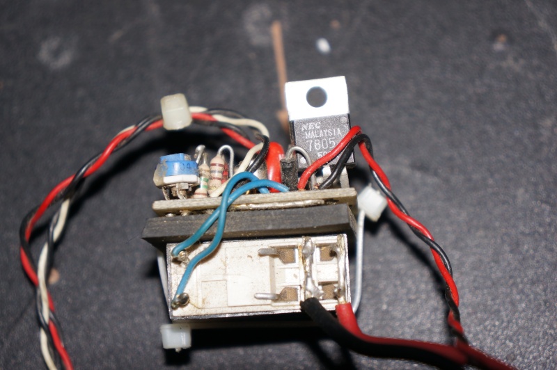
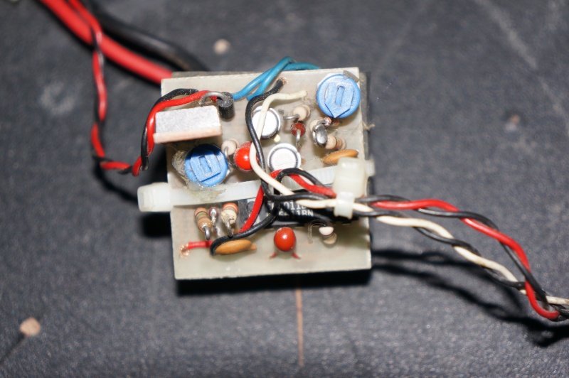
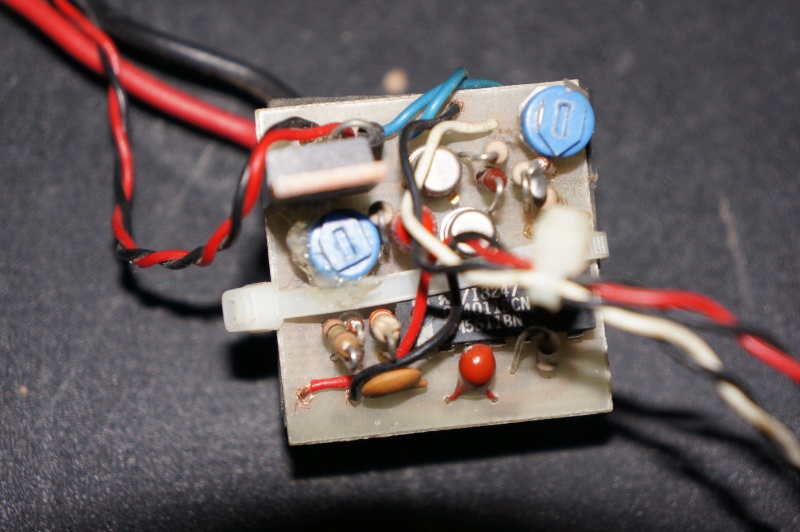
Hermann Mon Mar 05, 2012 6:03 pm
Hello Richard,
the new more close up photographs confirm my first estimation so I am sure that this is a switch unit. That big black device with marking "NEC Malaysia 7805..." is an integrated 5V fixed voltage regulator that provides a stabilised 5V supply for the electronics on that circuit board (or even for the receiver that is connected to, as a bec function). In front of it I can see a vertical mounted black diode that is the free wheeling diode for the relay coil. Beneath the wiring I can discover a 14 pin integrated circuit device of type CD 4011, a quadruple 2 input NAND Gate, here obviously used for generating a reference pulse and pulse length comparison (that is used for the switching point). The metal can transistors seem to be used to drive the relay coil and the potentiometers may be used to set the switch point.
@ Nigele: For the first moment I also thought about a reverse switch relay but in that case we would need both contact sets of center contact (C), normal closed contact (NC) and normal open contact (NO). Here only the center contacts (switched in parallel)and the normal open contacts (also switched in parallel) are wired and used.
Unfortunately the circuit board layout can't be seen conpletely so reconstruction of the circuit diagram is not possible yet. But I am quite sure that this is a switch.
Kind regards
Hermann
» Flight controllers as sub levelers
» Bournville 2023
» Raspberry Pi Pico + ePaper display hat
» WW2 mini sub build
» Help with 1:48 scale WW2 German U boat
» Problem with Futaba FX-30 and 40 MHz module
» Resurgam, Nordenfelts II & IV - George Garrett's works.
» Letter to BMFA to request the sharing of the 35MHz frequency for model subs in the UK.