


We are delighted to post another in-depth contribution from Hein Kistenich:
Propeller Balancer (15/1/2022)
I would like to start with the following consideration: The propeller converts the energy of the motor into propulsion. Driving machines, in our case electric motors, are industrially manufactured parts that do not need any improvements. The situation is different with the propellers, which are often self-made. Optimizing them is worthwhile. This includes, on the one hand, the adaptation of the propeller to the motor. I have also included two examples of what not to do.
Then it's about the "machine" propeller itself. As a rotating component, it is subject to the laws of centrifugal force, which - if present - is noticeable as an imbalance. The following balancer aims to reduce this imbalance or even eliminate it entirely.
The balancer was created during the restoration of the SUSHI model .
08/12/2021
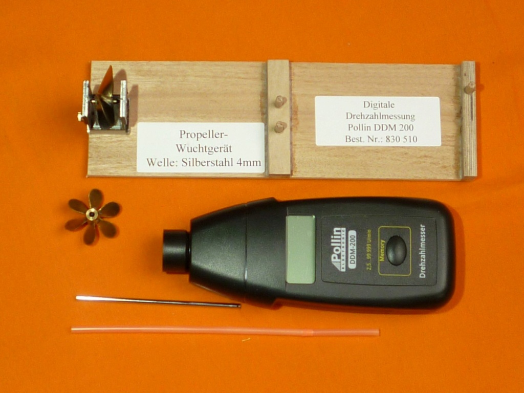
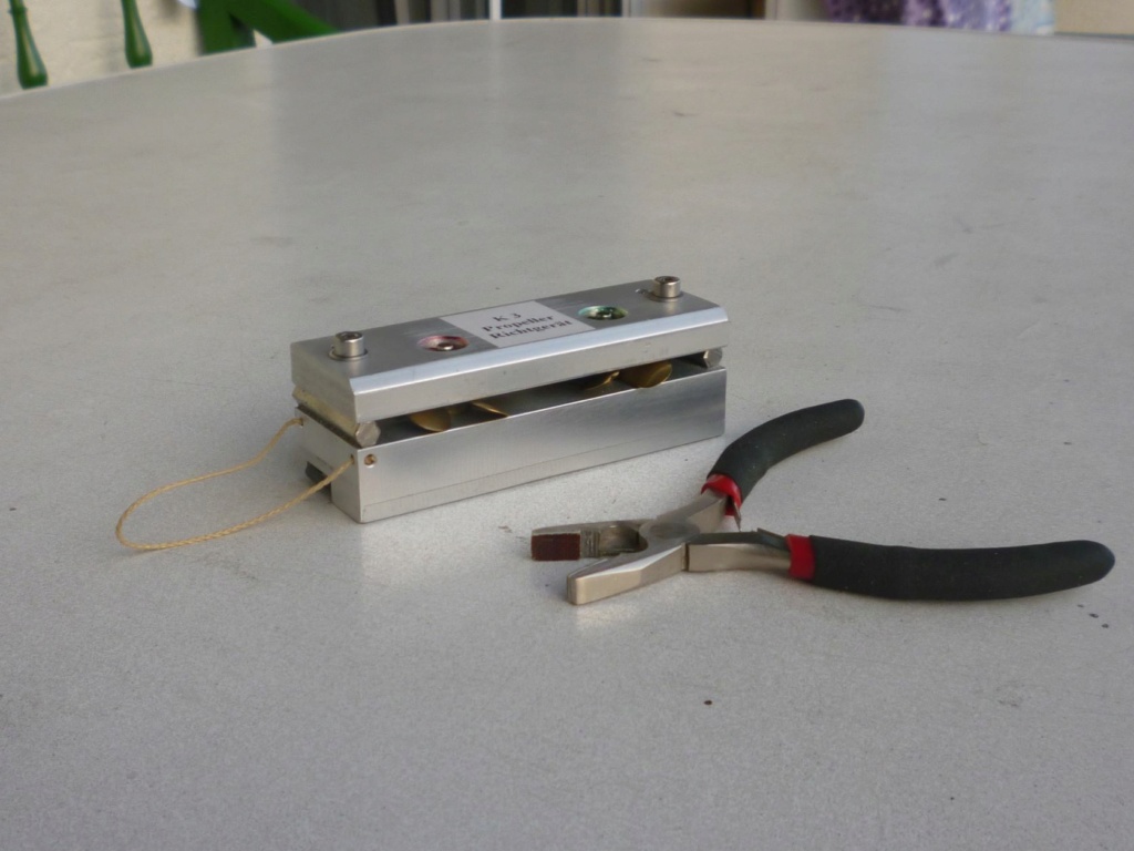
Construction of a simple balancing device.
The clever thing is that the propellor shaft hub is suspended between two magnets and so has very little friction.
The test hub is a silver steel shaft sharpened at both ends and is held in place by the two magnets. The stronger magnet only allows the shaft to rest on one side. A drop of oil on this bearing reduces the already low friction. The difference between before and after propeller balancing is amazing. Flexible needle files with different grits have proven themselves as useful tools for balancing the props.
The low friction means that the propeller can be spun up to high speeds with a compressed air jet. (Even blowing on the propeller through a drinking straw may be enough!)
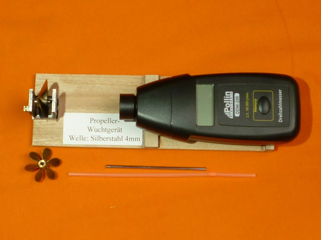
The propeller revs per minute (rpm) is measured with an electronic rev counter.
My rev counter device from Pollin sends a focused beam of light onto the rotating test object. There is a reflective mark on this (blackened) shaft. With each revolution, this mark reflects the beam of light from the meter, which is then shown on the display as revolutions per minute.
The balancer was constructed from a 50 mm long piece of aluminum square tube 25 x 25 mm and the walls were removed about 33 mm deep on two sides. The flaps that remained were doubled up with the waste material. Material of the same thickness was also placed on the foot. These pads are glued and riveted. Two 8 mm holes were drilled at the top, in each of which an 8 x 3 magnet was fixed. (See photos.)
This device can be used to test propellers up to a diameter of 56 mm and a hub length of no more than 20 mm.
Here are some logs of my trials:
K 3 model.
September 15th + 16th, 2021
On the 15th the port propeller was balanced. It took many hours.
Today, on the 16th, work with the starboard propeller went even faster.
The digital tachometer worked. At first, the propellers were powered by compressed air, but when the bottle ran out, lung power was used. However, I was by no means satisfied with the result, because in my "flying" setup not only the reflective mark on the propeller hub was measured, but sometimes the shadows cast by the propeller blades were also counted. I should repeat this work again under different conditions.
The purpose of this measure is to reduce the unavoidable residual imbalance (be it static or dynamic) to such an extent that the maximum speed of around 5,000 rpm to be expected during operation does not lead to vibrations in the shaft system.
If higher speeds can also be achieved without vibrations, all the better. But at least up to the limit speed, vibration-free operation should be possible.
The test hub is a silver steel shaft sharpened at both ends and is held in place by the two magnets. The stronger magnet only allows the shaft to rest on one side. A drop of oil on the bearing reduces the already low friction. The difference between before and after propeller balancing is amazing.Flexible needle files with different grits have proven themselves as useful tools for balancing the props.
The vibration of the drive train in the SUSHI had almost completely disappeared after this "cure".
Pursued goal:
In the ideal case, the test object remains still at the end of the rotation without any after-oscillation.
The speed measurement:
My digital measuring device from Pollin (DDM = digital speed meter) sends a focused beam of light onto the rotating test object. This can e.g., be a wave. There is a reflective mark on this (blackened) shaft. With each revolution, this mark reflects the beam of light from the meter, which is then shown on the display as revolutions per minute.
In my measuring device, the reflective mark is located behind the propeller, which now interrupts the measuring beam sent out with each rotation. In order to get a correct measurement result, the number shown on the display must be divided by the number of leaves.
If propellers with a larger diameter have to be checked, an adapted tool can be created very easily based on this knowledge.
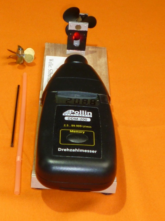
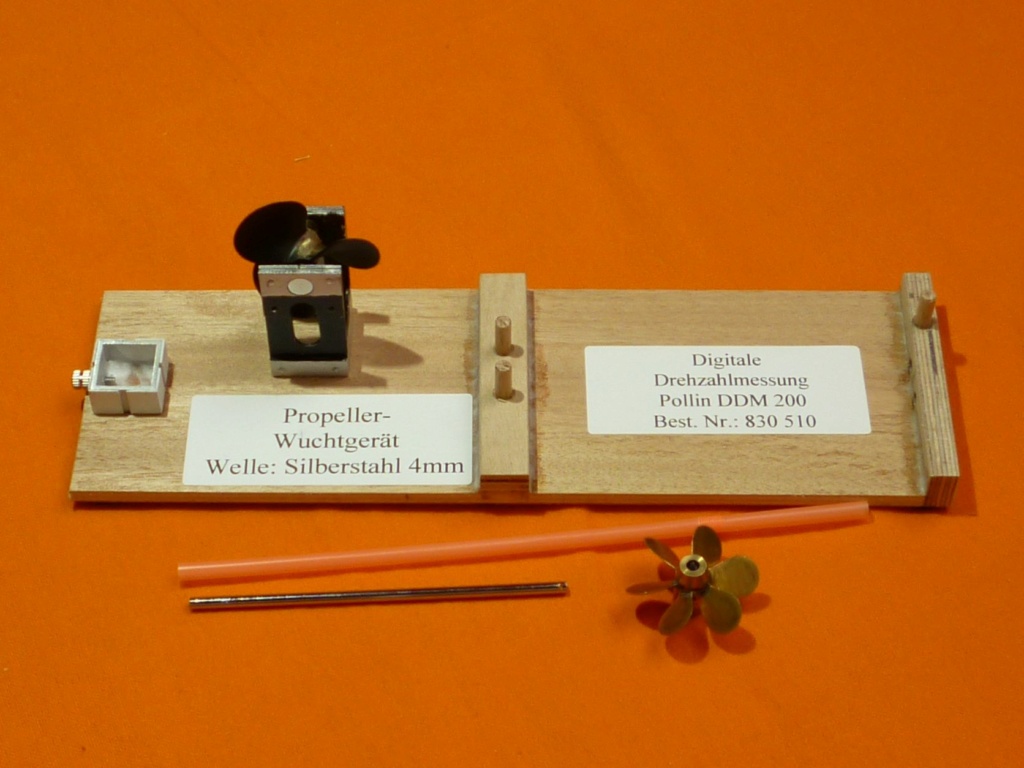
01/05/2022 Improvement of the measuring device
Today the SUSHI prop was improved again.
With another attempt to determine the speed of the propeller with my DDM, it quickly became clear that there was still a lot to do. So, a base board was prepared on which the DDM can be fixed. The magnet holder (test body) was mounted about 10 cm in front of the lens of the DDM in the focal point of the measuring beam. Before that, however, an 8 mm wide slot was milled vertically into the front. The holder heated up so much that the magnet above it lost some of its strength. This was replaced. The device was painted black (matt) on the front and also on the inside and a reflective foil was attached on the inside. The test specimen stands over a square base and is fixed with a screw.
01/05/2022 Measurement of the SUSHI propeller
Manufacturer: Prop-Shop (GB), Ø 48 mm, brass, trefoil, shape: St(andart) The speed of the SUSHI's propeller, which was set in rotation by blowing on a straw, could then be measured with the DDM. On a first try, the device showed 15,133 rpm. Dividing it by 3 gives around 5,044 rpm.
That is more than enough, because the new drive motor “only” reaches 4,200 rpm with the planned on-board voltage when idling.
In another test (blowing with compressed air), my colleague Wolfgang even reached a speed of around 30,000. He held the measuring device between his thumb and forefinger. The vibrations that occurred were barely perceptible.
Result: Because the vibration is negligible over the range between standstill and the speed to be expected in subsequent operation (4,200 rpm), nothing further is done at this point.
The propeller can now be used in the model!
Brief review of my experiences of the period 2000 to 2005.
It is hard to imagine what would have happened back then in the SUSHI with the old Hopf motor with its around 20,000 rpm and a (soft-soldered) Rabösch propeller. 2000 was the year my son Klaus lost his SUSHI.
In 2001, my colleague Nils first saw the soft-soldered propeller blades fly-off on his V 300 at the “Waschmühle”, a public bath near Kaiserslautern, and then, after he had found a replacement propeller somewhere, the Plettenberg machine fell apart on the next trip. Plettenberg www.info@plettenberg-motoren.com is a manufacturer of high-quality electric motors. Anyone who owned such an engine in the submarine model scene at the time was respected. His machine had a power consumption of around 1.000 watts.
Not unlikely that he got a cast and therefore more stable prop as a replacement. The prop was probably even stronger than the Pletti. (Plettenberg motor)
Luckily, an underwater sound recording was made before the accident, which - even many years later - keeps making the hairs on the back of my neck stand up.
A short time later, Nils reached a speed of 20 km/h under water with his V 300* (scale 1:30), now with a new engine and adapted propeller.
The same thing happened to our colleague Erwin, whose self-made prop had destroyed two beefy industrial engines from Bosch one after the other. The 7 crescent-shaped leaves come from curved brass carpet rails.
This prop has been on the Type 212 of colleague K.D.W. cloud. He can set up his (homemade) speed controller in such a way that the drive motor only draws as much current as his boss allows him. KDW did not change the pitch of the blades, but adjusted the power consumption of the motor to the propeller.
01/06/2022 Measurement of a K 3 propeller 6- sheet.
The unusable and therefore superfluous propeller of the K 3 (unusable because it was not properly brazed) reached a speed of 5,340 rpm in one test and even 5,790 rpm in another. Here, too, slight vibrations could be felt with the fingertips.

End Note:
For you fellow model builders, I am including some links to companies named in my "mental outpourings".
Coreless DC Motors:
https://www.maxongroup.co.uk/maxon/view/content/index
https://www.faulhaber.com/en/products/dc-motors/
Disc Motors:
https://www.baumueller.com/en/products/motors#top
Tip for the disc motor from Baumüller: I wasn't looking for this motor, the motor found me. At the beginning of the construction of STINT, a colleague gave me this example. We didn't know anything about the engine because there was no longer a nameplate. Only two boreholes reminded that something like this had once been there. Nevertheless, the engine was installed. Only after a few years did another colleague accidentally recognize this treasure and gave me copies of a prospectus. It turned out that I drive a 42 volt version in STINT. Life can be so beautiful.
High End electric motor manufacture
https://plettenberg-motoren.net/en/home
Speed models, tools:
https://www.hydromarine.de/index.php?language=en
Distributor for electronic parts:
https://www.pollin.de/
Norbert Brüggen, author, ROVs, submarine models, electronic parts:
https://www.tauchrobotershop.de
Best wishes
Hein
Propeller-Wuchtgerät
15.01.2022
Beginnen möchte ich mit folgender Überlegung: Der Propeller setzt die Energie der Antriebsmaschine in Vortrieb um. Antriebsmaschinen, in unserem Fall Elektromotore, sind industriell gefertigte Teile, an denen keine Verbesserungen nötig sind. Anders sieht es bei den Propellern aus, die oftmals in Eigenarbeit entstehen. Sie zu optimieren lohnt sich. Dazu gehört zum einen die Anpassung vom Propeller an den Motor. Weiter unten – im Zwischenspiel - finden sich zwei klassische Beispiele wie man es nicht machen sollte.
Dann geht es um die „Maschine“ Propeller selbst. Als rotierendes Bauteil unterliegt sie den Gesetzen der Fliehkraft, die sich - falls vorhanden - als Unwucht bemerkbar macht. Um diese Unwucht zu verringern, oder gar ganz zu beseitigen geht es im folgenden Aufsatz.
Anfangen möchte ich mit folgendem Beitrag, der bei der Restauration der SUSHI entstand.
12.08.2021
Bau eines kleinen Auswuchtgerätes.
Aus einem Alu-Vierkantrohr 25 x 25 mm wurde ein 50 mm langes Stück abgesägt und an zwei Seiten die Wände etwa 33 mm tief entfernt. Die stehen geblieben Laschen wurden oben mit dem Abfallmaterial aufgedoppelt. Auch am Fuß wurde gleich dickes Material aufgelegt. Diese Auflagen sind verklebt und vernietet. Oben wurden zwei 8 mm Löcher gebohrt, in die dann je ein Magnet 8 x 3 fixiert wurde.
Mit diesem Gerät können Propeller bis zu einem Durchmesser von 56 mm und einer Nabenlänge von nicht mehr als 20 mm geprüft werden.
Hier noch ein weiterer Nachtrag von der K 3
15. + 16.09.2021
Am 15. wurde der Bb-Propeller ausgewuchtet. Es hat Stunden gedauert.
Heute, am 16. ging die Arbeit mit dem Stb-Propeller umso schneller.
Dann wurde mit dem dig. Drehzahlmesser laboriert. Zunächst wurden die Propeller mit Druckluft angetrieben, als die Flasche aber leer wurde, ging es auch mit Lungenkraft. Mit dem Ergebnis war ich aber keineswegs zufrieden, weil in meinem „fliegenden“ Aufbau nicht nur die Reflexmarke auf der Propellernabe gemessen wurde, sondern manchmal auch die Schattenwürfe der Propellerblätter gezählt wurden. Diese Arbeit sollte ich unter anderen Bedingungen noch einmal wiederholen.
Sinn dieser Maßnahme soll sein, die unvermeidliche Restunwucht (sei sie nun statisch oder dynamisch) soweit zu reduzieren, dass die im Betrieb zu erwartende Höchstdrehzahl von etwa 5.000 Upm nicht zu Schwingungen der Wellenanlage führt.
Sollten auch höhere Drehzahlen ohne Schwingungen erreicht werden, umso besser. Aber zumindest bis zur Grenzdrehzahl sollte ein vibrationsloser Betrieb möglich sein.
Die Prüfnabe ist eine an beiden Enden angespitzte Welle aus Silberstahl und wird von den zwei Magneten in Position gehalten. Der stärkere Magnet lässt die Welle nur an einer Seite aufliegen. Ein Tropfen Öl an der Lagerstelle verringert die ohnehin schon geringe Reibung. Der Unterschied zwischen vor und nach dem Wuchten des Propellers ist erstaunlich. Als Werkzeug beim Wuchten haben sich elastische Nagelfeilen mit unterschiedlichen Körnungen bewährt.
Das Vibrieren des Antriebsstranges in der SUSHI war nach dieser „Kur“ fast gänzlich verschwunden.
Angestrebtes Ziel:
Im Idealfall bleibt der Prüfling am Ende der Rotation ohne jedes Nachpendeln still stehen,
Die Drehzahlmessung
Mein digitales Messgerät von Pollin (DDM = Digitaler Drehzahl-Messer) sendet einen bebündelten Lichtstrahl auf den rotierenden Prüfling. Dies kann z. B. eine Welle sein. Auf dieser (geschwärzten) Welle befindet sich eine Reflexmarke. Bei jeder Umdrehung reflektiert diese Marke den Lichtstrahl aus dem Messgerät, der dann als Umdrehung pro Minute auf dem Display angezeigt wird.
Bei meiner Messeinrichtung befindet sich die Reflexmarke hinter dem Propeller, der nun bei jedem Umlauf den ausgesandten Meßstrahl unterbricht. Um zu einem korrekten Messergebnis zu gelangen, muss die auf dem Display angezeigte Zahl durch die Anzahl der Blätter geteilt teilen,
Sollten einmal Propeller mit größerem Durchmesser zu prüfen sein, kann aufbauend auf diesen Erkenntnissen sehr leicht ein angepasstes Hilfsmittel erstellt werden.
05.01.2022 Verbesserung der Messeinrichtung
Heute wurde wieder am SUSHI-Prop geschliffen.
Bei einem weiteren Versuch, mit meinem DDM die Drehzahl des Propellers festzustellen, wurde schnell klar, dass da noch Einiges zu tun ist. Also wurde ein Grundbrett vorbereitet, worauf das DDM fixiert werden kann. Etwa 10 cm vor der Linse des DDM wurde im Brennpunkt des Meßstrahls der Magnethalter (Prüfköper) montiert.
Vorher wurde allerdings in die Vorderseite senkrecht noch ein 8 mm breiter Schlitz gefräst. Dabei erwärmte sich der Halter so stark, dass der darüber befindliche Magnet einen Teil seiner Kraft verlor. Er wurde ausgetauscht. Das Gerät wurde an der Vorderseite und ebenso von innen schwarz (matt) lackiert und innen wurde eine Reflexfolie angebracht.
Der Prüfkörper steht über einem quadratischen Sockel und wird mit einer Schraube fixiert.
05.01.2022 Messung des SUSHI-Propellers
Hersteller: Prop-Shop (GB), Ø 48 mm, Gelbguss, Dreiblatt, Form: St(andart)
Die Drehzahl des durch Anpusten mit einem Strohhalm in Rotation versetzten Propellers der SUSHI konnte dann mit dem DDM gemessen werden. Bei einem ersten Versuch zeigte das Gerät 15.133 Upm an. Durch 3 geteilt, ergibt das rund 5.044 Upm.
Das ist mehr als genug, denn der neue Antriebsmotor erreicht bei der geplanten Bordspannung im Leerlauf „nur“ 4.200 Upm.
Bei einer weiteren Prüfung (Anblasen mit Pressluft) hat mein Kollege Wolfgang sogar eine Drehzahl von rund 30.000 erreicht. Dabei hielt er die Messeinrichtung zwischen Daumen und Zeigefinger. Die dabei aufgetretenen Schwingungen waren gerade noch spürbar.
Ergebnis: Weil über den Bereich zwischen Stillstand bis zu der zu erwartenden Drehzahl im späteren Betrieb (4.200 Upm) die Vibration verschwindend gering ist, wird an dieser Stelle nichts weiter unternommen.
Der Propeller kann im Modell verwendet werden!
Zwischenspiel
Kurzer Rückblick auf die Zeit 2000 bis 2005.
Nicht auszudenken, was damals in der SUSHI bei dem alten Hopf-Motor mit seinen rund 20.000 Upm mit einem (gelöteten) Rabösch-Propeller geschehen wäre. 2000 war das Jahr, wo die SUSHI für meinen Sohn Klaus verloren ging.
Dem Kollegen Nils gingen in 2001 im Freibad Waschmühle in KL bei seiner V 300 zuerst die gelöteten Propellerblätter fliegen, und dann, nachdem er irgendwo einen Ersatzpropeller aufgetrieben hatte, zerlegte sich bei der nächsten Fahrt die Plettenberg-Maschine. Plettenberg www.info@plettenberg-motoren.com ist ein Hersteller von hochwertigen E-Motoren. Wer damals in der U-Boot-Modell Szene ein solches Triebwerk sein Eigen nannte, wurde respektiert. Seine Maschine hatte eine Stromaufnahme von rund 1.000 Watt.
Nicht unwahrscheinlich, dass er als Ersatz einen gegossenen und deswegen stabileren Prop erwischt hatte. Da war wohl der Prop noch stärker als der Pletti.
Zum Glück wurde vor der Havarie eine UW-Tonaufnahme gemacht, die mir – auch viele Jahre später – immer wieder die Nackenhaare sträubt.
Kurze Zeit später erreichte Nils mit seiner V 300 (Maßstab 1:30) jetzt mit neuem Motor und angepasstem Propeller unter Wasser eine Geschwindigkeit von 20 km/h.
Ähnlich erging es seinerzeit unserem Kollegen Erwin, dessen selbst gemachter Prop hintereinander zwei bullige Industriemotore von Bosch zerstört hatte. Die 7 sichelförmigen Blätter stammen von gewölbten Teppichschienen aus Messing.
Dieser Prop befindet sich seit 2005 am Typ 212 des Kollegen K.D. Wolk. Er kann seinen (selbstgestrickten) Drehzahlsteller so einrichten, dass der Antriebsmotor nur soviel Strom aufnimmt, wie sein Boss ihm zugesteht. KDW hat nicht die Steigung der Blätter verändert, sondern die Stromaufnahme des Motors dem Propeller angepasst.
06.01.2022 Messung eines K 3 Propellers
6- Blatt
Der unbrauchbare und deshalb überzählige Propeller der K 3 (unbrauchbar deshalb, weil unsauber hartgelötet), erreichte bei einem Versuch eine Drehzahl von 5.340 Upm, bei einem weiteren sogar 5.790 Upm. Auch hier waren leichte Schwingungen mit den Fingerspitzen zu fühlen.

Propeller Balancer (15/1/2022)
I would like to start with the following consideration: The propeller converts the energy of the motor into propulsion. Driving machines, in our case electric motors, are industrially manufactured parts that do not need any improvements. The situation is different with the propellers, which are often self-made. Optimizing them is worthwhile. This includes, on the one hand, the adaptation of the propeller to the motor. I have also included two examples of what not to do.
Then it's about the "machine" propeller itself. As a rotating component, it is subject to the laws of centrifugal force, which - if present - is noticeable as an imbalance. The following balancer aims to reduce this imbalance or even eliminate it entirely.
The balancer was created during the restoration of the SUSHI model .
08/12/2021
Construction of a simple balancing device.
The clever thing is that the propellor shaft hub is suspended between two magnets and so has very little friction.
The test hub is a silver steel shaft sharpened at both ends and is held in place by the two magnets. The stronger magnet only allows the shaft to rest on one side. A drop of oil on this bearing reduces the already low friction. The difference between before and after propeller balancing is amazing. Flexible needle files with different grits have proven themselves as useful tools for balancing the props.
The low friction means that the propeller can be spun up to high speeds with a compressed air jet. (Even blowing on the propeller through a drinking straw may be enough!)
The propeller revs per minute (rpm) is measured with an electronic rev counter.
My rev counter device from Pollin sends a focused beam of light onto the rotating test object. There is a reflective mark on this (blackened) shaft. With each revolution, this mark reflects the beam of light from the meter, which is then shown on the display as revolutions per minute.
The balancer was constructed from a 50 mm long piece of aluminum square tube 25 x 25 mm and the walls were removed about 33 mm deep on two sides. The flaps that remained were doubled up with the waste material. Material of the same thickness was also placed on the foot. These pads are glued and riveted. Two 8 mm holes were drilled at the top, in each of which an 8 x 3 magnet was fixed. (See photos.)
This device can be used to test propellers up to a diameter of 56 mm and a hub length of no more than 20 mm.
Here are some logs of my trials:
K 3 model.
September 15th + 16th, 2021
On the 15th the port propeller was balanced. It took many hours.
Today, on the 16th, work with the starboard propeller went even faster.
The digital tachometer worked. At first, the propellers were powered by compressed air, but when the bottle ran out, lung power was used. However, I was by no means satisfied with the result, because in my "flying" setup not only the reflective mark on the propeller hub was measured, but sometimes the shadows cast by the propeller blades were also counted. I should repeat this work again under different conditions.
The purpose of this measure is to reduce the unavoidable residual imbalance (be it static or dynamic) to such an extent that the maximum speed of around 5,000 rpm to be expected during operation does not lead to vibrations in the shaft system.
If higher speeds can also be achieved without vibrations, all the better. But at least up to the limit speed, vibration-free operation should be possible.
The test hub is a silver steel shaft sharpened at both ends and is held in place by the two magnets. The stronger magnet only allows the shaft to rest on one side. A drop of oil on the bearing reduces the already low friction. The difference between before and after propeller balancing is amazing.Flexible needle files with different grits have proven themselves as useful tools for balancing the props.
The vibration of the drive train in the SUSHI had almost completely disappeared after this "cure".
Pursued goal:
In the ideal case, the test object remains still at the end of the rotation without any after-oscillation.
The speed measurement:
My digital measuring device from Pollin (DDM = digital speed meter) sends a focused beam of light onto the rotating test object. This can e.g., be a wave. There is a reflective mark on this (blackened) shaft. With each revolution, this mark reflects the beam of light from the meter, which is then shown on the display as revolutions per minute.
In my measuring device, the reflective mark is located behind the propeller, which now interrupts the measuring beam sent out with each rotation. In order to get a correct measurement result, the number shown on the display must be divided by the number of leaves.
If propellers with a larger diameter have to be checked, an adapted tool can be created very easily based on this knowledge.
01/05/2022 Improvement of the measuring device
Today the SUSHI prop was improved again.
With another attempt to determine the speed of the propeller with my DDM, it quickly became clear that there was still a lot to do. So, a base board was prepared on which the DDM can be fixed. The magnet holder (test body) was mounted about 10 cm in front of the lens of the DDM in the focal point of the measuring beam. Before that, however, an 8 mm wide slot was milled vertically into the front. The holder heated up so much that the magnet above it lost some of its strength. This was replaced. The device was painted black (matt) on the front and also on the inside and a reflective foil was attached on the inside. The test specimen stands over a square base and is fixed with a screw.
01/05/2022 Measurement of the SUSHI propeller
Manufacturer: Prop-Shop (GB), Ø 48 mm, brass, trefoil, shape: St(andart) The speed of the SUSHI's propeller, which was set in rotation by blowing on a straw, could then be measured with the DDM. On a first try, the device showed 15,133 rpm. Dividing it by 3 gives around 5,044 rpm.
That is more than enough, because the new drive motor “only” reaches 4,200 rpm with the planned on-board voltage when idling.
In another test (blowing with compressed air), my colleague Wolfgang even reached a speed of around 30,000. He held the measuring device between his thumb and forefinger. The vibrations that occurred were barely perceptible.
Result: Because the vibration is negligible over the range between standstill and the speed to be expected in subsequent operation (4,200 rpm), nothing further is done at this point.
The propeller can now be used in the model!
Brief review of my experiences of the period 2000 to 2005.
It is hard to imagine what would have happened back then in the SUSHI with the old Hopf motor with its around 20,000 rpm and a (soft-soldered) Rabösch propeller. 2000 was the year my son Klaus lost his SUSHI.
In 2001, my colleague Nils first saw the soft-soldered propeller blades fly-off on his V 300 at the “Waschmühle”, a public bath near Kaiserslautern, and then, after he had found a replacement propeller somewhere, the Plettenberg machine fell apart on the next trip. Plettenberg www.info@plettenberg-motoren.com is a manufacturer of high-quality electric motors. Anyone who owned such an engine in the submarine model scene at the time was respected. His machine had a power consumption of around 1.000 watts.
Not unlikely that he got a cast and therefore more stable prop as a replacement. The prop was probably even stronger than the Pletti. (Plettenberg motor)
Luckily, an underwater sound recording was made before the accident, which - even many years later - keeps making the hairs on the back of my neck stand up.
A short time later, Nils reached a speed of 20 km/h under water with his V 300* (scale 1:30), now with a new engine and adapted propeller.
The same thing happened to our colleague Erwin, whose self-made prop had destroyed two beefy industrial engines from Bosch one after the other. The 7 crescent-shaped leaves come from curved brass carpet rails.
This prop has been on the Type 212 of colleague K.D.W. cloud. He can set up his (homemade) speed controller in such a way that the drive motor only draws as much current as his boss allows him. KDW did not change the pitch of the blades, but adjusted the power consumption of the motor to the propeller.
01/06/2022 Measurement of a K 3 propeller 6- sheet.
The unusable and therefore superfluous propeller of the K 3 (unusable because it was not properly brazed) reached a speed of 5,340 rpm in one test and even 5,790 rpm in another. Here, too, slight vibrations could be felt with the fingertips.


End Note:
For you fellow model builders, I am including some links to companies named in my "mental outpourings".
Coreless DC Motors:
https://www.maxongroup.co.uk/maxon/view/content/index
https://www.faulhaber.com/en/products/dc-motors/
Disc Motors:
https://www.baumueller.com/en/products/motors#top
Tip for the disc motor from Baumüller: I wasn't looking for this motor, the motor found me. At the beginning of the construction of STINT, a colleague gave me this example. We didn't know anything about the engine because there was no longer a nameplate. Only two boreholes reminded that something like this had once been there. Nevertheless, the engine was installed. Only after a few years did another colleague accidentally recognize this treasure and gave me copies of a prospectus. It turned out that I drive a 42 volt version in STINT. Life can be so beautiful.
High End electric motor manufacture
https://plettenberg-motoren.net/en/home
Speed models, tools:
https://www.hydromarine.de/index.php?language=en
Distributor for electronic parts:
https://www.pollin.de/
Norbert Brüggen, author, ROVs, submarine models, electronic parts:
https://www.tauchrobotershop.de
Best wishes
Hein
Propeller-Wuchtgerät
15.01.2022
Beginnen möchte ich mit folgender Überlegung: Der Propeller setzt die Energie der Antriebsmaschine in Vortrieb um. Antriebsmaschinen, in unserem Fall Elektromotore, sind industriell gefertigte Teile, an denen keine Verbesserungen nötig sind. Anders sieht es bei den Propellern aus, die oftmals in Eigenarbeit entstehen. Sie zu optimieren lohnt sich. Dazu gehört zum einen die Anpassung vom Propeller an den Motor. Weiter unten – im Zwischenspiel - finden sich zwei klassische Beispiele wie man es nicht machen sollte.
Dann geht es um die „Maschine“ Propeller selbst. Als rotierendes Bauteil unterliegt sie den Gesetzen der Fliehkraft, die sich - falls vorhanden - als Unwucht bemerkbar macht. Um diese Unwucht zu verringern, oder gar ganz zu beseitigen geht es im folgenden Aufsatz.
Anfangen möchte ich mit folgendem Beitrag, der bei der Restauration der SUSHI entstand.
12.08.2021
Bau eines kleinen Auswuchtgerätes.
Aus einem Alu-Vierkantrohr 25 x 25 mm wurde ein 50 mm langes Stück abgesägt und an zwei Seiten die Wände etwa 33 mm tief entfernt. Die stehen geblieben Laschen wurden oben mit dem Abfallmaterial aufgedoppelt. Auch am Fuß wurde gleich dickes Material aufgelegt. Diese Auflagen sind verklebt und vernietet. Oben wurden zwei 8 mm Löcher gebohrt, in die dann je ein Magnet 8 x 3 fixiert wurde.
Mit diesem Gerät können Propeller bis zu einem Durchmesser von 56 mm und einer Nabenlänge von nicht mehr als 20 mm geprüft werden.
Hier noch ein weiterer Nachtrag von der K 3
15. + 16.09.2021
Am 15. wurde der Bb-Propeller ausgewuchtet. Es hat Stunden gedauert.
Heute, am 16. ging die Arbeit mit dem Stb-Propeller umso schneller.
Dann wurde mit dem dig. Drehzahlmesser laboriert. Zunächst wurden die Propeller mit Druckluft angetrieben, als die Flasche aber leer wurde, ging es auch mit Lungenkraft. Mit dem Ergebnis war ich aber keineswegs zufrieden, weil in meinem „fliegenden“ Aufbau nicht nur die Reflexmarke auf der Propellernabe gemessen wurde, sondern manchmal auch die Schattenwürfe der Propellerblätter gezählt wurden. Diese Arbeit sollte ich unter anderen Bedingungen noch einmal wiederholen.
Sinn dieser Maßnahme soll sein, die unvermeidliche Restunwucht (sei sie nun statisch oder dynamisch) soweit zu reduzieren, dass die im Betrieb zu erwartende Höchstdrehzahl von etwa 5.000 Upm nicht zu Schwingungen der Wellenanlage führt.
Sollten auch höhere Drehzahlen ohne Schwingungen erreicht werden, umso besser. Aber zumindest bis zur Grenzdrehzahl sollte ein vibrationsloser Betrieb möglich sein.
Die Prüfnabe ist eine an beiden Enden angespitzte Welle aus Silberstahl und wird von den zwei Magneten in Position gehalten. Der stärkere Magnet lässt die Welle nur an einer Seite aufliegen. Ein Tropfen Öl an der Lagerstelle verringert die ohnehin schon geringe Reibung. Der Unterschied zwischen vor und nach dem Wuchten des Propellers ist erstaunlich. Als Werkzeug beim Wuchten haben sich elastische Nagelfeilen mit unterschiedlichen Körnungen bewährt.
Das Vibrieren des Antriebsstranges in der SUSHI war nach dieser „Kur“ fast gänzlich verschwunden.
Angestrebtes Ziel:
Im Idealfall bleibt der Prüfling am Ende der Rotation ohne jedes Nachpendeln still stehen,
Die Drehzahlmessung
Mein digitales Messgerät von Pollin (DDM = Digitaler Drehzahl-Messer) sendet einen bebündelten Lichtstrahl auf den rotierenden Prüfling. Dies kann z. B. eine Welle sein. Auf dieser (geschwärzten) Welle befindet sich eine Reflexmarke. Bei jeder Umdrehung reflektiert diese Marke den Lichtstrahl aus dem Messgerät, der dann als Umdrehung pro Minute auf dem Display angezeigt wird.
Bei meiner Messeinrichtung befindet sich die Reflexmarke hinter dem Propeller, der nun bei jedem Umlauf den ausgesandten Meßstrahl unterbricht. Um zu einem korrekten Messergebnis zu gelangen, muss die auf dem Display angezeigte Zahl durch die Anzahl der Blätter geteilt teilen,
Sollten einmal Propeller mit größerem Durchmesser zu prüfen sein, kann aufbauend auf diesen Erkenntnissen sehr leicht ein angepasstes Hilfsmittel erstellt werden.
05.01.2022 Verbesserung der Messeinrichtung
Heute wurde wieder am SUSHI-Prop geschliffen.
Bei einem weiteren Versuch, mit meinem DDM die Drehzahl des Propellers festzustellen, wurde schnell klar, dass da noch Einiges zu tun ist. Also wurde ein Grundbrett vorbereitet, worauf das DDM fixiert werden kann. Etwa 10 cm vor der Linse des DDM wurde im Brennpunkt des Meßstrahls der Magnethalter (Prüfköper) montiert.
Vorher wurde allerdings in die Vorderseite senkrecht noch ein 8 mm breiter Schlitz gefräst. Dabei erwärmte sich der Halter so stark, dass der darüber befindliche Magnet einen Teil seiner Kraft verlor. Er wurde ausgetauscht. Das Gerät wurde an der Vorderseite und ebenso von innen schwarz (matt) lackiert und innen wurde eine Reflexfolie angebracht.
Der Prüfkörper steht über einem quadratischen Sockel und wird mit einer Schraube fixiert.
05.01.2022 Messung des SUSHI-Propellers
Hersteller: Prop-Shop (GB), Ø 48 mm, Gelbguss, Dreiblatt, Form: St(andart)
Die Drehzahl des durch Anpusten mit einem Strohhalm in Rotation versetzten Propellers der SUSHI konnte dann mit dem DDM gemessen werden. Bei einem ersten Versuch zeigte das Gerät 15.133 Upm an. Durch 3 geteilt, ergibt das rund 5.044 Upm.
Das ist mehr als genug, denn der neue Antriebsmotor erreicht bei der geplanten Bordspannung im Leerlauf „nur“ 4.200 Upm.
Bei einer weiteren Prüfung (Anblasen mit Pressluft) hat mein Kollege Wolfgang sogar eine Drehzahl von rund 30.000 erreicht. Dabei hielt er die Messeinrichtung zwischen Daumen und Zeigefinger. Die dabei aufgetretenen Schwingungen waren gerade noch spürbar.
Ergebnis: Weil über den Bereich zwischen Stillstand bis zu der zu erwartenden Drehzahl im späteren Betrieb (4.200 Upm) die Vibration verschwindend gering ist, wird an dieser Stelle nichts weiter unternommen.
Der Propeller kann im Modell verwendet werden!
Zwischenspiel
Kurzer Rückblick auf die Zeit 2000 bis 2005.
Nicht auszudenken, was damals in der SUSHI bei dem alten Hopf-Motor mit seinen rund 20.000 Upm mit einem (gelöteten) Rabösch-Propeller geschehen wäre. 2000 war das Jahr, wo die SUSHI für meinen Sohn Klaus verloren ging.
Dem Kollegen Nils gingen in 2001 im Freibad Waschmühle in KL bei seiner V 300 zuerst die gelöteten Propellerblätter fliegen, und dann, nachdem er irgendwo einen Ersatzpropeller aufgetrieben hatte, zerlegte sich bei der nächsten Fahrt die Plettenberg-Maschine. Plettenberg www.info@plettenberg-motoren.com ist ein Hersteller von hochwertigen E-Motoren. Wer damals in der U-Boot-Modell Szene ein solches Triebwerk sein Eigen nannte, wurde respektiert. Seine Maschine hatte eine Stromaufnahme von rund 1.000 Watt.
Nicht unwahrscheinlich, dass er als Ersatz einen gegossenen und deswegen stabileren Prop erwischt hatte. Da war wohl der Prop noch stärker als der Pletti.
Zum Glück wurde vor der Havarie eine UW-Tonaufnahme gemacht, die mir – auch viele Jahre später – immer wieder die Nackenhaare sträubt.
Kurze Zeit später erreichte Nils mit seiner V 300 (Maßstab 1:30) jetzt mit neuem Motor und angepasstem Propeller unter Wasser eine Geschwindigkeit von 20 km/h.
Ähnlich erging es seinerzeit unserem Kollegen Erwin, dessen selbst gemachter Prop hintereinander zwei bullige Industriemotore von Bosch zerstört hatte. Die 7 sichelförmigen Blätter stammen von gewölbten Teppichschienen aus Messing.
Dieser Prop befindet sich seit 2005 am Typ 212 des Kollegen K.D. Wolk. Er kann seinen (selbstgestrickten) Drehzahlsteller so einrichten, dass der Antriebsmotor nur soviel Strom aufnimmt, wie sein Boss ihm zugesteht. KDW hat nicht die Steigung der Blätter verändert, sondern die Stromaufnahme des Motors dem Propeller angepasst.
06.01.2022 Messung eines K 3 Propellers
6- Blatt
Der unbrauchbare und deshalb überzählige Propeller der K 3 (unbrauchbar deshalb, weil unsauber hartgelötet), erreichte bei einem Versuch eine Drehzahl von 5.340 Upm, bei einem weiteren sogar 5.790 Upm. Auch hier waren leichte Schwingungen mit den Fingerspitzen zu fühlen.

» David Forrest's R class
» Futaba -868/915mhz equipment
» Darnell type 21 submarine, need some help
» Robbe Seawolf V2
» bladder bags
» WW2 mini sub build
» Peral Submarine of 1888
» U-Boat R/C?