Who is online?
In total there are 20 users online :: 0 Registered, 0 Hidden and 20 Guests :: 1 Bot
None
Most users ever online was 180 on Tue Nov 05, 2019 6:03 am
Latest topics
Search
Most Viewed Topics
Statistics
Our users have posted a total of 12477 messages in 1986 subjects
We have 1017 registered users
The newest registered user is Bazdiving
Similar topics
27Mhz - Radio Ideas

geofrancis- Posts : 293
Join date : 2021-09-24
- Post n°51
 Re: 27Mhz - Radio Ideas
david f likes this post

david f- AMS Treasurer
- Posts : 2407
Join date : 2010-11-10
Age : 73
Location : Cumbria
- Post n°52
 Re: 27Mhz - Radio Ideas
2.4 GHz can be used with a trailing surface aerial i.e no underwater performance.
The LoRa system at 433/458 MHz looks good and I have been using it on two of my model subs for several months. Underwater performance and telemetry are good features. Hardware is up to date and available. The frequency legislation does not make it much good for "global" development (e.g a Licence needed in US).
27 MHz systems are much more problematic. Good underwater performance but not much possibility for telemetry. Hardware is difficult (see thoughts below). This frequency does represent a "global" possibility with the only competitive use being toys and die-hard CB enthusiasts.
27 MHz hardware development thoughts:
- Buy 2nd hand. Only very old gear available and not dirt cheap.
- The AX5043 chip is up to date, low cost, easy to make legal and would look to have potential but is complex and only suitable for development professionals (certainly not me!)
- Radiometrix modules . These look good but are rather too expensive.
- Raspberry Pi and SDR approaches. Show potential but I wonder what would be involved in making them legal?
See also:
http://www.icrobotics.co.uk/wiki/index.php/Turning_the_Raspberry_Pi_Into_an_FM_Transmitter
- Cheap Chinese Toy modules. Just because they can be imported doesn't necessarily mean they are legal?! Trials show they could be used "as is" for small, simple submarines. Further development would be difficult. (See notes below.)
David
Notes on development of cheap Chinese models - pictured in earlier post.
I have been able to send a PPM stream to the RX. A scope shows something like a correct waveform but I haven't been able to get a PPM decoder (see photo) to give a PWM servo signal. (I tried an invertor circuit also.) I had to re-tune the TX, for some reason, to stay within the 27MHz (CB) band.) These TXs do not use crystals.
For anyone wanting to build on this, here is what I tried;
- TX board. I cut the PCB trace leaving pin 6 and injected the PPM signal.
- RX board. I tapped off the signal at pin 16 of the chip.
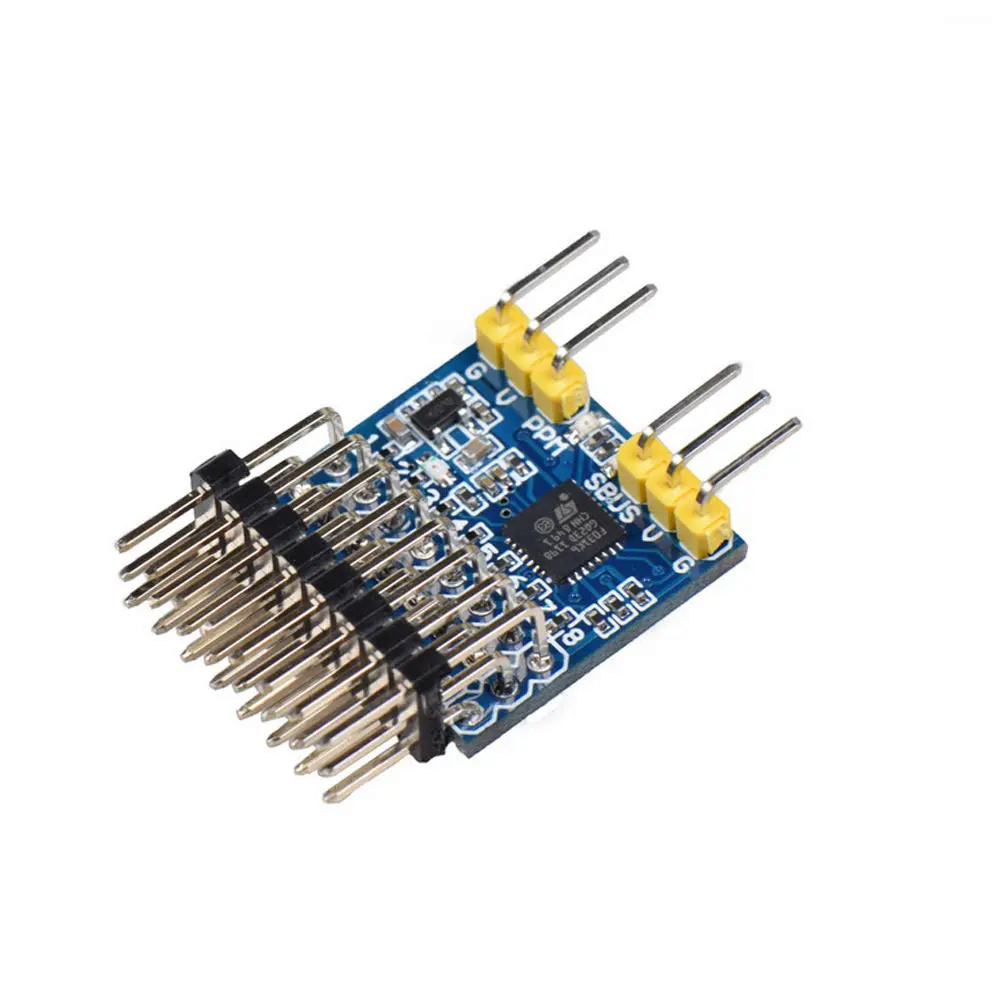
JHEMCU SPP 8CH Signal Converter Module Support SBUS PPM PWM Output for Receiver
ID: 1549017 (Banggood UK)
Price:US$8.76
geofrancis likes this post

geofrancis- Posts : 293
Join date : 2021-09-24
- Post n°53
 Re: 27Mhz - Radio Ideas
david f wrote:To summarize my views so far.
2.4 GHz can be used with a trailing surface aerial i.e no underwater performance.
The LoRa system at 433/458 MHz looks good and I have been using it on two of my model subs for several months. Underwater performance and telemetry are good features. Hardware is up to date and available. The frequency legislation does not make it much good for "global" development (e.g a Licence needed in US).
27 MHz systems are much more problematic. Good underwater performance but not much possibility for telemetry. Hardware is difficult (see thoughts below). This frequency does represent a "global" possibility with the only competitive use being toys and die-hard CB enthusiasts.
27 MHz hardware development thoughts:
- Buy 2nd hand. Only very old gear available and not dirt cheap.
- The AX5043 chip is up to date, low cost, easy to make legal and would look to have potential but is complex and only suitable for development professionals (certainly not me!)
- Radiometrix modules . These look good but are rather too expensive.
- Raspberry Pi and SDR approaches. Show potential but I wonder what would be involved in making them legal?
See also:
http://www.icrobotics.co.uk/wiki/index.php/Turning_the_Raspberry_Pi_Into_an_FM_Transmitter
- Cheap Chinese Toy modules. Just because they can be imported doesn't necessarily mean they are legal?! Trials show they could be used "as is" for small, simple submarines. Further development would be difficult. (See notes below.)
David
Notes on development of cheap Chinese models - pictured in earlier post.
I have been able to send a PPM stream to the RX. A scope shows something like a correct waveform but I haven't been able to get a PPM decoder (see photo) to give a PWM servo signal. (I tried an invertor circuit also.) I had to re-tune the TX, for some reason, to stay within the 27MHz (CB) band.) These TXs do not use crystals.
For anyone wanting to build on this, here is what I tried;
- TX board. I cut the PCB trace leaving pin 6 and injected the PPM signal.
- RX board. I tapped off the signal at pin 16 of the chip.
JHEMCU SPP 8CH Signal Converter Module Support SBUS PPM PWM Output for Receiver
ID: 1549017 (Banggood UK)
Price:US$8.76
I am waiting for the same ppm converter and 27mhz modules, I will replicate your setup as soon I can.
As for the legality, these chinese toys have been sold since probably the 80s, they operate at such low power levels that just no one cares. There is nothing critical on 27mhz, the only people still using it are the CB radio usesrs but half of them are running 100w+ amps so could care less about our 10mw toys. the main reason its went away is 27mhz is really susceptible to interference from modern switching power supplies, it's the same reason you dont see medium wave or longwave radios in cars anymore because it's a problem to filter out the switching noise.
Last edited by geofrancis on Sat Jan 22, 2022 4:04 pm; edited 1 time in total
david f likes this post

david f- AMS Treasurer
- Posts : 2407
Join date : 2010-11-10
Age : 73
Location : Cumbria
- Post n°55
 Re: 27Mhz - Radio Ideas
Firstly, I'm very impressed by the ability of the Pi to produce a 27MHz signal (I still find it hard to believe!). (This trace shows the transmission of a regular tone burst. (pulses.wav from the software))
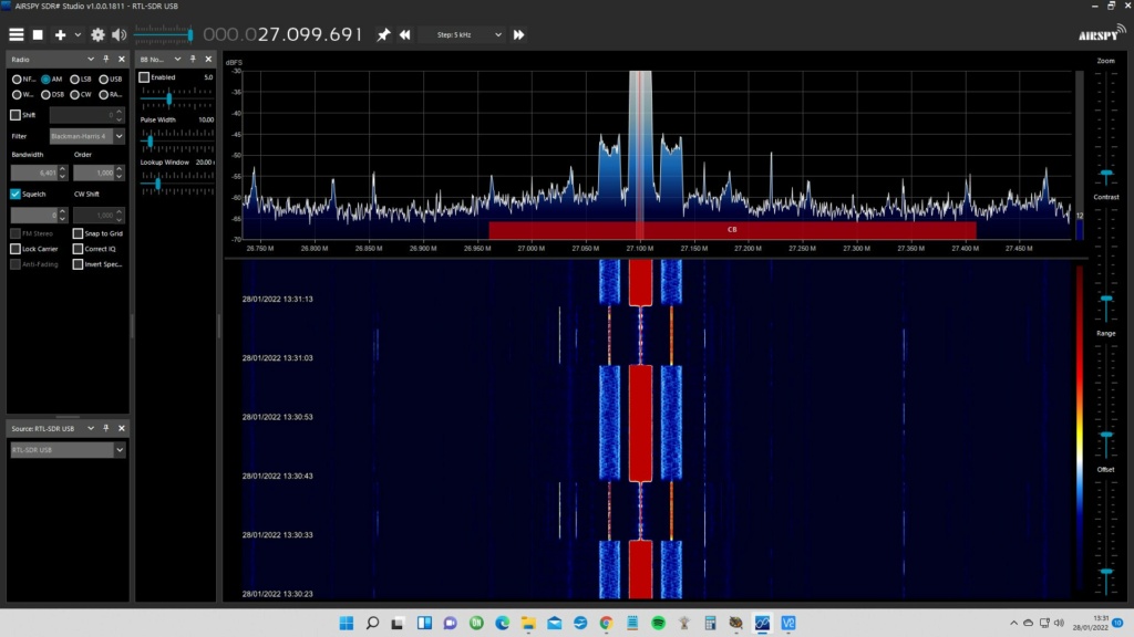
The use of Raspberries means that the equipment is quite small and could fit in a submarine.
Still a long way to go in terms of (any) development. The best range I got was only about 5m using the simple piano wire ones form the Chinese modules.
I found that the following sets of instructions worked for me. (many didn't!). Both Pi's were installed with the up to date versions of the Raspbian operating system.
For the TX using a Raspberry Pi 3
https://github.com/mundeepl/PiFM
For the RX using a Raspberry Pi 4 and a standard and (cheap!) RTL-SDR using the RTL2832U chip:
https://hamprojects.wordpress.com/2020/09/06/raspberry-pi-for-ham-radio/
This tutorial downloaded from the above website was particularly useful:
RPI part 3-V1.3 Using RTL-SDR Key;
Last edited by david f on Sat Jan 29, 2022 9:51 am; edited 3 times in total
SimonH and geofrancis like this post

SimonH- Posts : 92
Join date : 2020-09-29
Location : Nottingham, UK
- Post n°56
 Re: 27Mhz - Radio Ideas
One source I found is http://www.proto-advantage.com/store/product_info.php?products_id=2200069
that seem to make the QFN28 to DIP adapter PCB and can assemble a user specified chip to it, with a price quoted of £4.20 when I entered the Dikey part (AX5043-1-TW30).
This would probably not work for UHF but at 27MHz is probably OK.
The idea would be to gat a batch made so providing at least a supply of modules that can be used with hand soldering skills, I might go down to 0.05"/1mm but 0.5mm spacing would make me reach for a good technician at work!
Actualy not sure you could use a soldering iron however good you are as the pads are underneath the chip so some form of hot air/hot plate is used in the small set-ups I've used in various companies but I've also seen board de-laminate due to too much heat.
This still leaves the actual design to be done, but that is realy 'just' the chip to antenna filter/impedance adapter network, the rest seems to be digital, assuming an Arduino/Pi type controller.
Looking at the schematic, the coils from ant pins to GND are simply DC coupling so probably aren't critical, havent looked at the others in detail.
david f likes this post

david f- AMS Treasurer
- Posts : 2407
Join date : 2010-11-10
Age : 73
Location : Cumbria
- Post n°57
 Re: 27Mhz - Radio Ideas
I now have some AX5043 chips and some break out boards and I intend to have a go at soldering them when my Quick hot air rework station arrives (but will probably take months from China at the moment!)
(I have been wanting to have go at SMD devices for some time at John Robinson's original suggestion and I don't mind messing some parts up as part of my learning curve.)
BUT, as you say, if they are available commercially at that kind of price then that is the way to go.
Simon wrote:The matching circuit for the antenna is certainly a bit of a monster though the link you included does seem to have a lot of detail in it.
This matching circuit worries me, as you say, Simon. I think even the inductors would need to be SMD devices, but my knowledge of RF components is a bit limited. With your knowledge of production is there any way this could be manufactured at a reasonable price?
LATER EDIT:
Thinking a bit more about this, maybe just the Class E network section would be required for early trials and wouldn't be too daunting to build with a mix of DIY wound inductors or
https://www.ebay.co.uk/itm/113710838065?hash=item1a79b1b131:g:dBIAAOSwm-1cqda3
etc? (Sometimes I wish I was a HAM!)


SimonH- Posts : 92
Join date : 2020-09-29
Location : Nottingham, UK
- Post n°58
 Re: 27Mhz - Radio Ideas
I was thinking of adding in the values for the 169MHz version and sweeping from 100MHz to 200MHz to see what happened, driving from a 50ohm source at the antenna and starting with 50ohms load at the ANTN & ANTP pins, i.e. simulating the Rx effect.
I'm guessing that the inductors from ANTN/ANTP to gnd are needed to provide a DC path, possibly some kind of open source/open drain type switching output.
The balun is probably needed to convert what looks like a sort of push-pull double output to a single. You could make a try, but I'm guessing that each output switches on for each half-cycle and would cut outout by half and also the Rx side by half (probably more) so would inpact on range a lot. Its probably quite a broadband network so hopefully not too critical.
Obviously for 27MHz the values are different but should scale by sqrt(f) I think but not sure.
From those values round the inductors to prefered values as its easier to get varied cap values in general, but check the SRF (self resonant frequency) of the inductors' data sheet to make sure its well above 27MHz.
Having found the inductors pick the caps but possibly drop a few pF to allow for strays.
As you say, the filter could be ignored for now, esp if you connect direcly to your sofware radio/scope or whatever.
Changing the L/C ratio in the balun might be needed to optimise as I think that sets the impedance conversion, but I'm not a ham either! Not sure what data is given on the pin impedance at 27MHz.
I seem to recall from my youth that 27MHz antenna on the Tx tended to have a loading coil in the middle so it didn't need to be 1/2 wave, but antenna theory is even more arcane than 'normal' RF to me so you might have to tweak the balun to match the Tx/Master antenna on the one unit and the Rx/slave wire on the other.
Appologies if you already knew all that, but LTspice is worth a look at, I find it quick and easy to simulate little analogue snippets. For PCB layouts etc. I use Eagle CAD, also a free tool and good for smallish boards, but there are several options there as well.
Have fun!
david f likes this post

david f- AMS Treasurer
- Posts : 2407
Join date : 2010-11-10
Age : 73
Location : Cumbria
- Post n°59
 Re: 27Mhz - Radio Ideas
This plot shows (I think!) the frequency plot for the final filter in the antenna matching circuit. Presumably this is to minimise harmonics in the 27MHz signal.
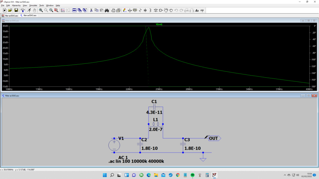
Thinking more about this complete antenna circuit, I don't think it will be that difficult to make, for a trial prototype anyway. Using wired components and "dead- bug" construction will be quite easy and I understand works well for RF circuits. (e.g less capacitance between components.)
I tried but did not succeed in ordering an AX5043 chip fitted to an adapter board from Proto Advantage.
Not VERY cheap at €16.92 but when I clicked on the final order I got this message:
"Some of the parts we are purchasing for you are not rated EAR99. Unfortunately due to export restrictions we only ship this parts to United States and Canada. Please remove the assembled ICs from your cart and we can process your order. If you believe you've received this message in error please contact us at: info@proto-advantage.com or (888) 880-0297."
So we proceed, albeit a bit slowly due to the vagaries of global trade! I will wait for my rework station to arrive from China and then try soldering what chips I have. (Ironically the chips I recently received were also from China and were probably manufactured there so I don't understand the export restriction!)
But I think we may be able to breathe some new technological life into 27MHz for use in our hobby. My concerns are now with the digital side. I have found a developed library for the AX5043 and the Raspberry Pi on Github which may provide insights:
https://github.com/BrandenburgTech/DigitalTxRxRPi
Yes, I remember that all my Dad's 27MHz transmitters had loading coils in their already bulky aerials. I have observed that one or two yachties in our club, still using 27MHz, find the transmitter aerials very handy for recovering models!
Thanks again for the tip about LTspice.
David
Last edited by david f on Mon Feb 07, 2022 8:11 am; edited 1 time in total
SimonH likes this post

SimonH- Posts : 92
Join date : 2020-09-29
Location : Nottingham, UK
- Post n°60
 Re: 27Mhz - Radio Ideas
In general I would always have a series resistance in the voltage source and a restive load to make it more realistic.
I also had a rumage arround and found a couple of web sites that might help:
http://rfic.eecs.berkeley.edu/~niknejad/ee242/pdf/eecs242_class_EF_PAs.pdf
https://people.physics.anu.edu.au/~dxt103/class-e/
these deal with how to match class E outputs. It looks as if the matching is dependant on the voltage swing and load impedance. I did re-create an excel spreadsheet from the equations which seems to work, with the idea of using the data sheet values for 169MHz to see if I could reverse engineer the output switching resistance, voltage switch and load impedance, but though close not an exact match, seeing as all are unkown. I can't see a way of posting the spread sheet here if anyone is interested.
It looks as if the idea is to get the time response of the current and voltage to be what is wanted, but you can do time based simulation in LTspice as well, using a pulsed voltage source (or 2) as the source. I seem to recall making a time opperated switch is more tricky but can be done and is a better model for the Tx outputs that seem to be open drain/open gate type configuration.
For Baluns search for 'lumped balun', I found various and this looks helpfull: http://educypedia.karadimov.info/library/Balun%20Design.pdf
The balun will convert the 50 unbalanced to some other impedance (haven't tried calculating yet) which then becomes the load impedance for the class E networks. As far as I can see the idea is to get the phase shift at the working frequency to be +90 or -90 for each arm so giving 180 between arms i.e. balanced.
simples!!
david f likes this post

SimonH- Posts : 92
Join date : 2020-09-29
Location : Nottingham, UK
- Post n°61
 Re: 27Mhz - Radio Ideas
david f likes this post

david f- AMS Treasurer
- Posts : 2407
Join date : 2010-11-10
Age : 73
Location : Cumbria
- Post n°62
 Re: 27Mhz - Radio Ideas

SimonH- Posts : 92
Join date : 2020-09-29
Location : Nottingham, UK
- Post n°63
 Re: 27Mhz - Radio Ideas
I've been having a bit of a play with LTspice creating models for the 169MHz version given and extrapolating down to 27MHz, and I think the trick might be to look at them in the time domain rather than frequency domain.
I only have pdfs at home as my simulator is at work at the moment, so I hope they come across OK.
the 169MHz model is

whilst the 27MHz version is
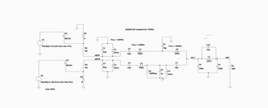
To model the driver outputs (i.e. in Tx mode) I've used a pulsed source with two diodes and a source resistor so that it is a bit like an open drain/source driver.
both pulsed sources have a 50:50 on/off ratio with a fast rise/fall time, but the 'antn' source is delayed by half cycle to give the 180 deg phase shift.
I can't show many results but some are
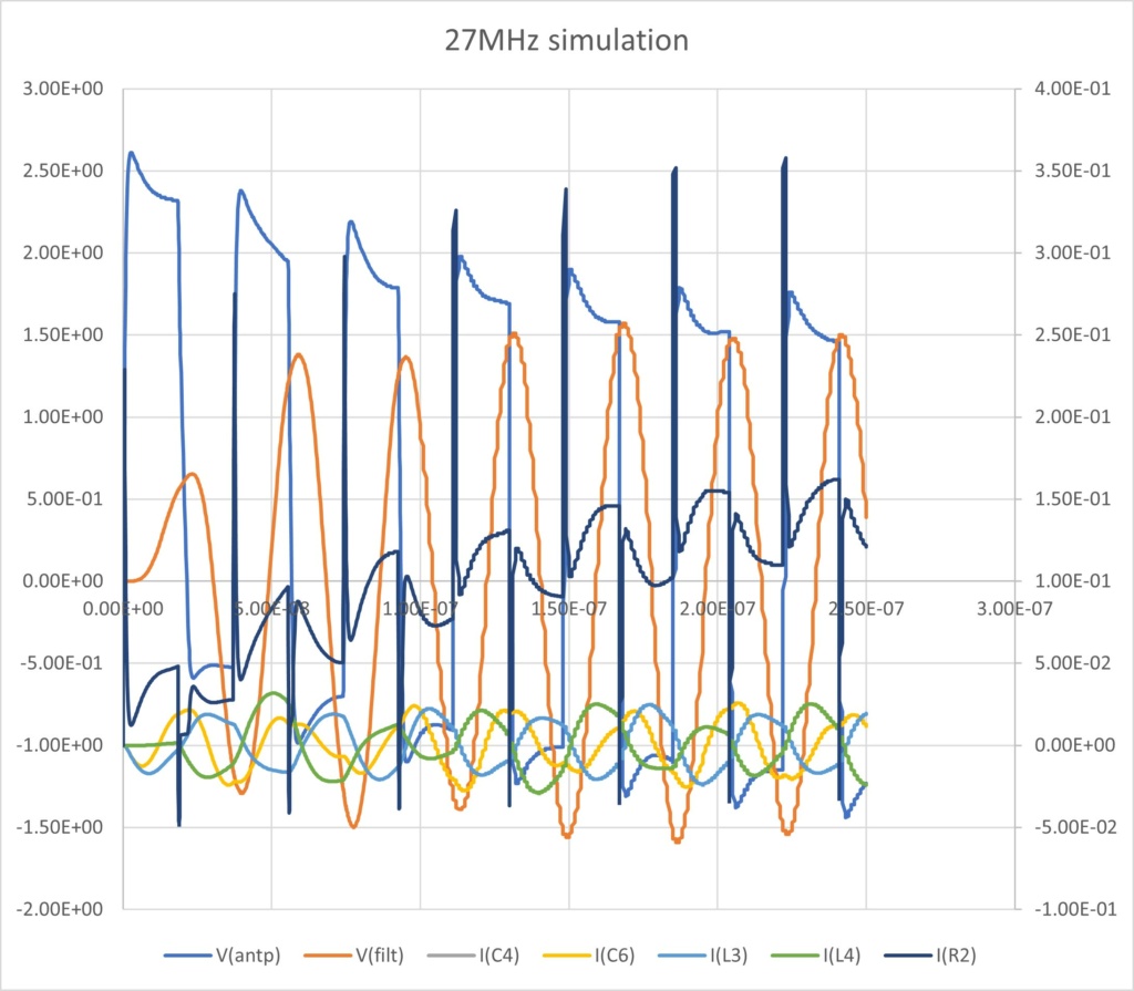
They rapidly get very cluttered, even more so if you try to add both phases!. The results shown are actualy a chart in an excel spread sheet from data exported from LTSpice so all a bit complicated.
They seem to show that the rise/fall times of the currents though L3 and L4 show a rise time of about half cycle, so that just as the current peaks the drive switches off. The voltage at 'filt' or 'ant' is then the sum of the pull & push from each half and generates a reasonable sine wave.
There is a bit of a startup time of a few cycles as every thing reaches some kind of equilibrium, but it looks plausible.
The scaling from 269MHz to 27MHz was simply multiplying each component by 6.25 (i.e. 169/27) and the pulsed sources period from 6nsec to 37nsec.
All a bit approx but does look reasonable, in theory :)
david f likes this post

SimonH- Posts : 92
Join date : 2020-09-29
Location : Nottingham, UK
- Post n°64
 Re: 27Mhz - Radio Ideas
david f likes this post

david f- AMS Treasurer
- Posts : 2407
Join date : 2010-11-10
Age : 73
Location : Cumbria
- Post n°65
 Re: 27Mhz - Radio Ideas
It is a bit like Class D audio (digital) amplifiers which I remember a few decades back were still regarded as a theoretical possibility but I now listen to the radio using one!
My hot air rework thingy has just arrived so I hope to be getting my physical hands on an AX5043 with connections I can get to!
David

david f- AMS Treasurer
- Posts : 2407
Join date : 2010-11-10
Age : 73
Location : Cumbria
- Post n°66
 Re: 27Mhz - Radio Ideas

Hardware (See photo).
This went together quite well. The initially rather daunting RF antenna section was actually OK using components with leads assembled on a "dead-bug" basis using some tinplate as a ground plane. (I am using the circuit configuration for 433MHz to begin with.)
My hot air re-work station seemed to do a good job of making the break out boards. (See photo)
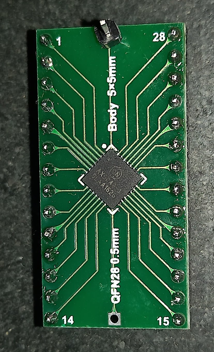
Actually such a good job of making these, for not much money, that if anyone contributing to this project would like one (I have 2 or 3 available) for free, let me know. (On the basis that you report back with details of your success or failure. I could probably also dig out the components for the RF section if it would help.)

Initial Testing (See photo)
The chips all seemed to generate some RF carrier output when powered up. The marked dotted line on the "waterfall" is me sending morse by powering off the chip!
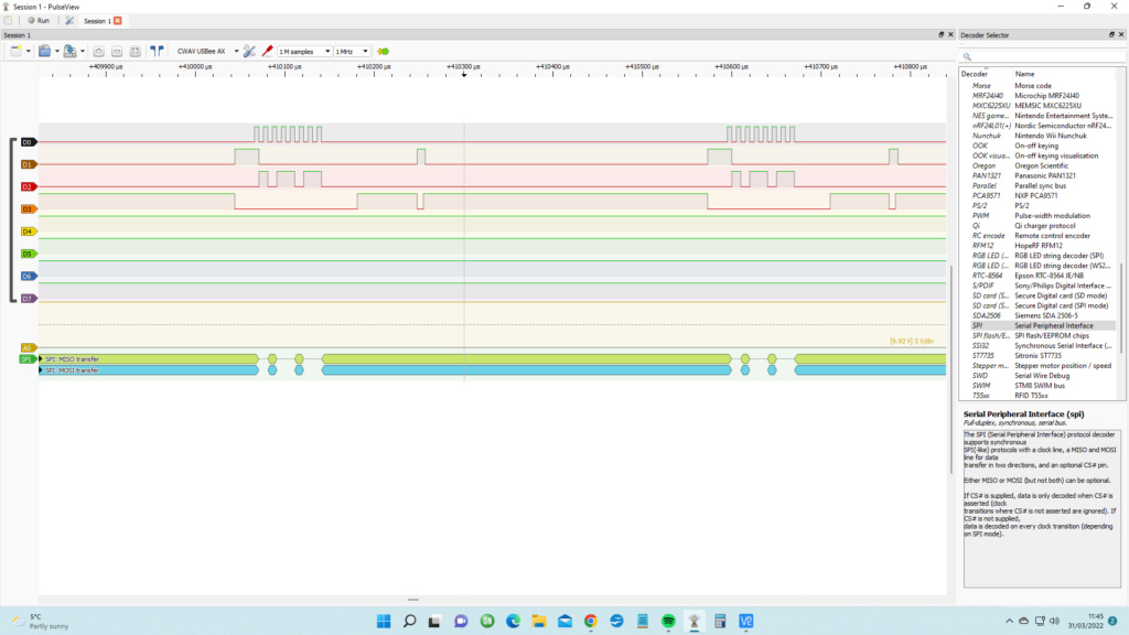
I have been able to analyse the SPI connection with a logic analyzer but this is early days - I'm learning. (See photo)
Communicating with the chip.
All my attempts have been made using a Raspberry Pi Zero with up to date Debian operating system. (The Zero would be just about practical in an RX and TX in terms of size and power consumption (I am not that familiar with the Raspberry Pi and this has contributed to my problems so far.)
I was hoping that existing software from contributors to Github would work easily and quickly. WRONG! I have had difficulty in getting the software available to compile, link and run. (I don't want to use the expensive test gear offered by the chip manufacturer and the much criticized Radiolab software. )
It would be very useful if anyone with more experience could get the software to run so I will go over the different sources in some detail:
https://github.com/BrandenburgTech/DigitalTxRxRPi
This is very comprehensive and I used his schematics for my hardware. It has been written for the Raspberry Pi and the AX5043 but it is complicated and I cannot run the software. Help please!
https://github.com/richardeoin/ax
This is clearly written and I can get the python software to run. But sadly it is written for the Raspberry Pi and two AX5243 chips - so it is difficult to adapt.
https://github.com/UTRocketry/AX5043-Radio
This was written with the Arduino in mind (Which is probably the way to go for a practical RX in subs. The Pico may be a contender eventually but see my other post today) but it is incomplete and has not been worked on for 3 years.
So, somewhat limited progress. Help with compiling software and ideas would be much appreciated.
I am pleased to say that I am very content with the Lora system on 458 MHz for my subs. I don't use anything else now in my models.
Background OFCOM information on r/c in UK:
https://www.ofcom.org.uk/spectrum/radio-spectrum-and-the-law/licence-exempt-radio-use/licence-exempt-devices/Radio-controlled-models
David
SimonH likes this post

C-3PO- Posts : 95
Join date : 2018-11-21
Location : Northamptonshire UK
- Post n°67
 Re: 27Mhz - Radio Ideas
Always up for a challenge - if you still have any of those boards going I would be interested to give it a go getting them to fire.
If you do, let me know and I will send you my address (not sure how) - happy to drop some money to you via PayPal to cover post and board cost
Recently been working on a new concept of pitch controller/leveller - very promising - trials will tell if it's any good.....
Regads
Jonathan _._
david f likes this post

SimonH- Posts : 92
Join date : 2020-09-29
Location : Nottingham, UK
- Post n°68
 Re: 27Mhz - Radio Ideas
SPI should be a standard protocol that simply transfers data, so the lowest level should be code that can drive any SPI 'peripheral' such as a display or anything else. the RF bits should just be able to specify a sequence of register addresses and data values that need to be sent, with some code that inokes the SPI send (or receive) function and passes the address and data.
There should be any number of SPI libraries, even if not built in, but it might be worth considering having 2 cpu systems to start with, with one being a dummy RF module that can be used to debug the SPI traffic. In fact, it should be possible to connect a 2nd 'monitor' function in parallel though you would only be able to monitor one direction at a time.
The other option might be to create a realy simple app that requests an address/data pair via the kbd and then sends it, You could check that it works by sending data to simething like an SPI display module or some other known SPI thingy, then move on to hand setting up the RF module.
Hopefully the RF module will accept a data value to send at any time, i.e. not requiring a constant data stream.
I've found that seperating what you want to send and the method of sending is helpfull when trying to write control s/w for any kind of black box, but quite often have ended up noddy bits of code to just send user defined data as a proof of concept then create the app that sends that data that you have already tested.
The board looks good, building with BGAs is impresive.
david f likes this post

david f- AMS Treasurer
- Posts : 2407
Join date : 2010-11-10
Age : 73
Location : Cumbria
- Post n°69
 Re: 27Mhz - Radio Ideas
The problem seems to be connected to the SPI clock pulse. To my untutored eye D0 on the photo doesn't look like a nice regular clock. (This is connected to Pin 15 on the AX5043.)

The screen shot shows the Raspberry running Richard Meadows Python software which seems to run OK and the output from a logic analyser.
I will do some quick tests to see if I have the crystal set up correctly.
Thanks for the suggestions about testing the SPI communication, Simon. I have just put a MAX7219 SPI 8 digit Red 7 segment LED display module on order.
I will be pleased to send you a board, Jonathan but I would like to confirm that SPI is working first so that I don't send you a "bad-un." (We can exchange addresses by PM on this Forum)
Thanks again for the help. The major hurdle is getting the chip "talking."
David
Last edited by david f on Thu Apr 14, 2022 8:13 am; edited 1 time in total

C-3PO- Posts : 95
Join date : 2018-11-21
Location : Northamptonshire UK
- Post n°70
 Re: 27Mhz - Radio Ideas
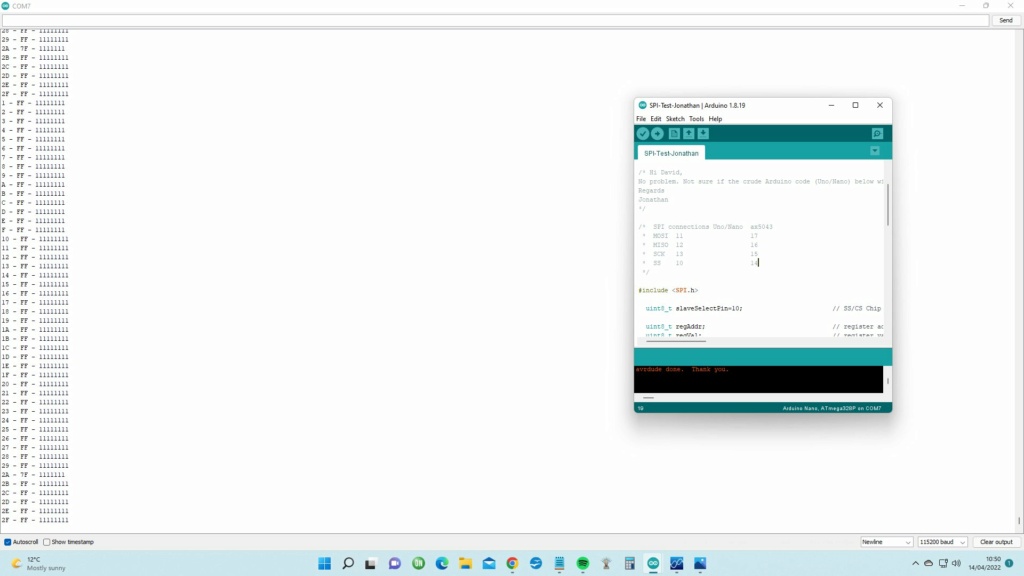
No problem. Not sure if the crude Arduino code (Uno/Nano) below will help you - it's a very simple SPI grab of register values. Might help prove that your SPI is working or not. You should be able to see some register values in the serial monitor...
Regards
Jonathan
- Code:
// ***********************************************************************************************
//  Name:       spiTest_005.ino
//  Date:       17 Mar 2015
//  Brief:      Crude SPI test
//  Author:     Jonathan Askey
// ***********************************************************************************************


/*  SPI connections Uno/Nano
 *  MOSI  11
 *  MISO  12
 *  SCK   13
 *  SS    10
 */

#include <SPI.h>

  uint8_t slaveSelectPin=10;                        // SS/CS Chip Select

  uint8_t regAddr;                                  // register address
  uint8_t regVal;                                   // register value

  uint8_t xSPCR;                                    // SPCR – SPI Control Register
  uint8_t xSPSR;                                    // SPSR – SPI Status Register

  unsigned long loopInterval = 2000;
  unsigned long loopPreviousMillis = 0;

void setup() {

  digitalWrite(slaveSelectPin, HIGH);               // set SS/CS pin high
  pinMode(slaveSelectPin, OUTPUT);                  // set the SS pin as an output
  SPI.begin();                                      // initialize the SPI library
  SPI.beginTransaction(SPISettings(14000000, MSBFIRST, SPI_MODE0));

  Serial.begin(115200);                             // start serial
}

void loop() {

  if (millis() - loopPreviousMillis > loopInterval)
  {

      digitalWrite(slaveSelectPin, LOW);             // set the SS pin to LOW

          for ( regAddr = 1; regAddr <= 0x2F; regAddr++)
          {
           xSPCR=SPCR;                                // SPCR – SPI Control Register - take a copy
           xSPSR=SPSR;                                // SPSR – SPI Status Register - take a copy
            SPI.transfer(regAddr & 0x7F);             // send address + r/w bit
            regVal = SPI.transfer(0);

            Serial.print(regAddr, HEX);
            Serial.print(" - ");
            Serial.print(regVal,HEX);
            Serial.print(" - ");
            Serial.println(regVal,BIN);
          }

      digitalWrite(slaveSelectPin, HIGH);             // set the SS pin HIGH

      SPCR=xSPCR;                                     // SPCR – SPI Control Register - restore
      SPSR=xSPSR;                                     // SPSR – SPI Status Register - restore

      loopPreviousMillis=millis();
  }
}
david f likes this post

C-3PO- Posts : 95
Join date : 2018-11-21
Location : Northamptonshire UK
- Post n°71
 Re: 27Mhz - Radio Ideas
I had some further thoughts - if you do not get any register data back from the AX5043 you may want to run my code against a RFM69 transceiver - this will should you how it the SPI commands spit out the register details.
Writing to the registers is as easy as reading, however before any "test" writing you need to know what was in the register in the first place so you can set it back to the original value after the test session (factory reset) or you could cause more frustration.
Regards
Jonathan _._

david f- AMS Treasurer
- Posts : 2407
Join date : 2010-11-10
Age : 73
Location : Cumbria
- Post n°72
 Re: 27Mhz - Radio Ideas
Would there any register values present when the chip is just powered up? I will have a go with an RFM69.
I have added the ax5043 pins I have used on your code.

C-3PO- Posts : 95
Join date : 2018-11-21
Location : Northamptonshire UK
- Post n°73
 Re: 27Mhz - Radio Ideas
Pinouts look good and I think it looks like SPI is working.
Looks like register 2A contains 7F ?
It's possible of course that the registers are "empty 11111111" and nothing has been written to them since production- I thought as you had been testing them with some Pi code they would have had some entries.
I will send you some code later that reads an address, then writes a value to that address, reads it to see if it stored your "write" and then finally reset it back to it's original status.
It might also be worth expanding the range of registers - amend this line of code
for ( regAddr = 1; regAddr <= 0x2F; regAddr++)
to
for ( regAddr = 1; regAddr <= 0x4F; regAddr++)
or even
( regAddr = 1; regAddr <= 0xFF; regAddr++)
Regards
Jonathan
david f likes this post

david f- AMS Treasurer
- Posts : 2407
Join date : 2010-11-10
Age : 73
Location : Cumbria
- Post n°74
 Re: 27Mhz - Radio Ideas
I also tried your suggestion of interrogating an RFM69. I actually used the Lora module (RFM95) because I had one to hand. It too returned all 11111111s.
I have been continuing my attempts to talk to the AX5043 using a Raspberry Pi Zero via SPI, with some limited success.
I initially tested the Zero SPI routine with a 7 segment display with poor results - too many conflicting "Guides" online!
I had more joy with connecting the Zero to an Arduino:
https://roboticsbackend.com/raspberry-pi-master-arduino-uno-slave-spi-communication-with-wiringpi/
I then included this software in the Brandenburg Github project (which has always been my hope for getting something already established, to work.).
I have still had to exclude major parts of this software to get it to compile and run. The problem with the Brandenburg software not working "out of the box" may be that a lot of changes have occurred (e.g the WiringPi software) with the Raspberry Pi since it was written.
Anyway here are the results:

The last two entries on Zero Terminal show 2 runs. One with the SPI connections disconnected.
So I am (fairly!) confident that the AX5043 chip is a "good-un". The chips all seem to transmit a narrow band on 433MHz.
On that basis, if you or any other person contributing to this project would like one (I have 2 or 3 available) for free, let me know and send me your address by PM. (On the basis that you report back with details of your success or failure. I could probably also dig out the components for the 433 MHz RF section if it would help.)
David
SimonH likes this post

david f- AMS Treasurer
- Posts : 2407
Join date : 2010-11-10
Age : 73
Location : Cumbria
- Post n°75
 Re: 27Mhz - Radio Ideas
Have fun and good luck with the project!
David
The RF output matching circuit for 27MHz comes from an onsemi forum thread here:
https://www.onsemi.com/forum/t/faq-how-to-operate-ax5043-at-27-mhz-custom-matching-networks-for-ax5043/274
(The diagram in post number 57 on this thread comes from the above source.)



» David Forrest's R class
» Futaba -868/915mhz equipment
» Darnell type 21 submarine, need some help
» Robbe Seawolf V2
» bladder bags
» WW2 mini sub build
» Peral Submarine of 1888
» U-Boat R/C?