The Association of Model Submariners.

Would you like to react to this message? Create an account in a few clicks or log in to continue.

* THE FORUM FOR ALL THOSE INTERESTED IN BUILDING AND OPERATING MODEL SUBMARINES *


Join the AMS - Registered Forum users can become members of the AMS and it's free ...... To join send an email with your name , address and phone number to amstreasure@googlemail.com


For a guide to past events see the "Shows and Events" section.

Papplewick Pumping Station SUBMARINE Day. 31st March - 1st April 2024.

$$$

&&&

::::

Who is online?

In total there are 5 users online :: 0 Registered, 0 Hidden and 5 Guests

None


Most users ever online was 180 on Tue Nov 05, 2019 6:03 am

Latest topics

» Information on camouflage patterns for German seahund
WW2 mini sub build EmptyFri Mar 15, 2024 4:36 pm by david f

» WW2 mini sub build
WW2 mini sub build EmptyTue Mar 12, 2024 1:56 pm by geofrancis

» Not the hobby I expected :)
WW2 mini sub build EmptySun Mar 10, 2024 6:30 pm by cat

» 868/915 Mhz as a viable frequency for submarines.
WW2 mini sub build EmptyWed Mar 06, 2024 4:50 pm by tsenecal

» Sheerline gasket material
WW2 mini sub build EmptyMon Feb 19, 2024 9:24 pm by Michaelc

» Choice of CAD software and Printer for 3D printing
WW2 mini sub build EmptyThu Feb 15, 2024 1:53 pm by david f

» Engel Nautlus
WW2 mini sub build EmptyTue Feb 13, 2024 9:15 am by palmert6

» RF 27/433MHz maximum depth in pools (1-5 ppm chlorine, 6-8pH)
WW2 mini sub build EmptyThu Feb 08, 2024 2:05 pm by david f

» Arduino proportional control of a piston tank
WW2 mini sub build EmptyThu Feb 08, 2024 1:37 pm by david f

Statistics

Our users have posted a total of 12425 messages in 1980 subjects

We have 1003 registered users

The newest registered user is Stefan Udovenko КПДЮ

Similar topics

5 posters

    WW2 mini sub build

    avatar
    SimonH


    Posts : 91
    Join date : 2020-09-29
    Location : Nottingham, UK

    WW2 mini sub build Empty WW2 mini sub build

    Post  SimonH Wed Jun 09, 2021 11:06 pm

    After some preliminary design & build I thought I'd share the fun(!)
    I've always been interested in submarines and even though about building a human sized version, but probably best I didn't my boatbuilduing skills are not that good in plywood.....
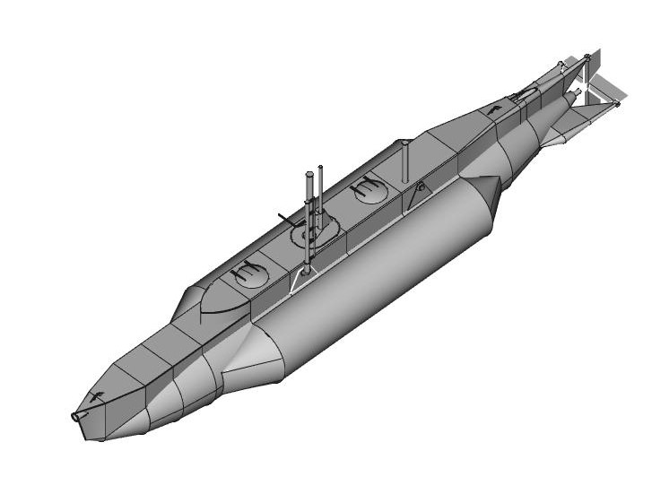
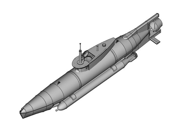
    However, as covid lock-down struck in 2020 I was was made redundant so decided to see what I could do with the CAD package FreeCAD, and based on photos & other drawings from the internet I generated some reasonable representations of Seehund & X-class as both appeal to me as models. I find the modern subs a bit anonymous, a bit like steam trains vs. diesel, possibly contentious but thats my preference. I then realised I had designed as full size so had to repeat a lot of the work to scale them down to about 1m, based on 110mm drain pipe fro the centre sections.
    WW2 mini sub build X-clas10

    and

    WW2 mini sub build Seehun10

    Neither will be museum standard, I subscribe to the 'measure with a micrometer, mark with chalk, cut with an axe' philosophy, but I aim to give areasonable likeness.

    Starting from scratch, I have no box of bits to raid, so the first task was a workable radio control system, bothered me less than mechanical stuff as I work in electronics. So the autumn to spring '21 was getting the 458MHz system going, with less time available now as I am back at work. I'm not going to add much on that as most is on the UHF radio control forum. For interest I use the EagleCAD package for electronics & PCB design as it is also free up to about 100mm x 100mm or so.

    Current plan is a peristaltic pump & bladder type system having discounted the idea of using a bicycle CO2 system as too risky and dangerous for a 1st model, but I decided I would build the inards up bit by bit and see how long a WTC I needed, based on a 75mm dia tube.
    Since I don't have a 3d printer the end caps are probably going to be cast resin based on a simple wooden master and all fitted into an outer hull made from 110mm drain pipe with fibreglass end sections. I don't want to go to the effort of making a complete mould for the fibreglass so I'm thinking of moulding over foam that I can then cut away rather than trying to disolve in acetone or similar solvent.
    The Seehund appeals as it has the lower tube to the pressure hull that I might use to hold the batteries to keep them central as they may be a major weight.

    After help from the brushless motor forum I have gone for the G2 Hydra15 system and now have the basic motor and gearbox with a 9:1 reduction using timing belts.

    WW2 mini sub build Dsc02715

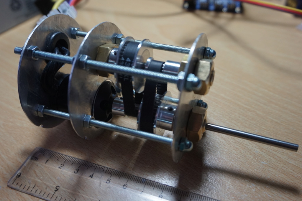
    I shall probably re-make a lot of it, but the basic setup seems OK.
    I have found that freecad is difficult to cut & bash metal from, so I use SolidEdge a free 2D drawing package to create traditional style drawings of the various peice-parts.
    Fortunately I have had for many years a myford ML10 lathe so boring the brass bolts for the shafts & layshaft ball-races is fairly straight forward.

    Current task is the brackets that hold the servos & routing the control rods past the motor & belt drive pulleys. Again made from aluminium sheet which can bolt onto the fwd end of the moter/gearbox assy.
    In front of that I intend to switch to perspex for the support of the ESC and PWM servo board.
    But that will be another post.

    david f, subkraft, Robbert de Rouw, Seehund Willy and geofrancis like this post

    avatar
    SimonH


    Posts : 91
    Join date : 2020-09-29
    Location : Nottingham, UK

    WW2 mini sub build Empty ESC & servos added

    Post  SimonH Sun Jun 20, 2021 10:13 pm

    I've now added the servos & control rods and some supports for the ESC & PWM driver board. I use the PWM board to drive the servos & on/off channels rther than generate in the Rx, so the Rx feeds data to the PWM board that generates actual servo controls.
    WW2 mini sub build Dsc02717

    As you can see the only way I managed to get the servos (mini size) in is back to back with one control rod either side,that seemed to be the only spare space in the 'gear box' area.
    Originally I intended to mount the servos on top the frames, but I moved them outwards so they didn't foul the rubber grommet I fitted to the hole used for the motor wires. Having though about it I think I will move them back inwards and simply not mount them direclty to the fwd motor frame, but on top of the end nuts as they currently are. That means I don't loosen the motor/belt drive frames if I need to remove them.
    At the moment one control rod has an O-ring between the brass bolt and cap nut, but I need to make another a test it for water-tightness as I am not convinced it will work as:
    1. the inside of the cap nut is not a good finish, and being stainless steel I'm not sure I can get in there to machine it flat
    2. the thread of the cap nut is also not perfect so I'm not sure the cap nut will screw right down onto the end of the bolt
    3. the only groove for the O-ring would be a simple counter sink on both parts.
    I'm thinking of either trying the bellows option or using a bigger control rod a it passes through the seal, I've tried to leave enough space for a bigger bolt for the seal, so could try either.
    WW2 mini sub build Dsc02718

    I've changed to 'perspex' for the ESC/PWM board mount as I don't need the mechanical strength or rigidity, but I think 1.5mm is a bit lightweight. As the servo mounting plates have moved outwards and the PWM board supports are longer than intended you can see it wouldn't fit in the intended 75mm tube envelope, so I need to re-make the servo plates and revise my 3D model to get it centred a bit more. I was hoping to get the ESC capacitor tucked inbetween the servo plates, but the capacitor is at the opposite end to the motor wires so maybe not.
    WW2 mini sub build Dsc02719

    WW2 mini sub build Dsc02720

    I didn't make the ESC mounting plate longer as I have not fixed as to what comes next. The idea is to have the Rx right at the bow end, with the ballast pump in the middle, so the next task is to get the perristaltic plump & control relays and see how they can be fitted. The relays can be driven by the same PWM board, but I am half expecting to have to design a solid state relay board as the standard relay boards might be too big to fit, but we'll see.

    david f likes this post

    avatar
    SimonH


    Posts : 91
    Join date : 2020-09-29
    Location : Nottingham, UK

    WW2 mini sub build Empty Re: WW2 mini sub build

    Post  SimonH Sat Jul 17, 2021 10:23 pm

    I've now managed to get all the control functions onto the prototype inards:
    WW2 mini sub build Dsc02721
    From the right are motor & 9:1 belt reduction gear, servos, PWM servo board & ESC behind, dual 5V relay module to control pump, 12V pump, another relay module (intended for an emergency rescue float), 458MHz reciever and finally a 12V master on/off relay. The last item is from '12V planet' and seems to be a standard auto type, but it has an integrated fuse holder, supplied with a 20A car fuse. I may replace  that with a 5A to 10A though.
    Not that vissible are the 0V & 12V busbars, one either side of the pump, basicaly 2 aluminium strips with M3 screws as terminals. At the minute the connections are a bit rough, but M3 crimp terminals seem to be on long leadtimes! In the final version the master relay will be controlled via a reed relay and magnet so I don't need another hole in the WTC. Electrical connections to the WTC will probably be via M3 screw terminals rather than a proper waterproof connector.
    The glass at the back is to check the pump works, and the 12V lead-acid battery is in the forground.
    The total length is about 575mm, so a WTC of about 600mm x 75mm dia which is a bit longer than I hoped. I can save some space as there is a bit of a gap between the antenna and the master relay. I did think about trying to fit the relay down the side of the antenna, but decided against it as I didn't know what effect on reception it might have.
    All electronic systems I have worked on have always had power protection of some kind to limit fault damage, so I was getting a bit twichy about have no fuses, but at least I have one now. I was thinking about designig a PCB to hold a few minitaure car blade fuses as the only option seemed to be the inline fuse holders , but even they are quite big, but I don't think the benifits are worth the effort & space.
    I think for the real thing I will use GRP sheet, as the perpex is easy to work but very floppy and doesn't seem to glue very well, some of the joints have already come apart. possibly with a solvent based glue it might be OK.
    Obviously the bladder is external to the WTC and I think I'll have another sealed resovoir as I'm not keen on pressurising the WTC. This is because I'm intending to swap to 4mm for all shafts and use 4x9x2 seals which might vent if the internal pressure is higher than outside. The Seehund would be just the job with its double tube hull design, but we'll see.  
    I'm also intending to go with a 'wet' lead-acid battery. The one shown is a 12V 2.3Ahr and the current is about 1.8A at max motor speed which seems like a good match.

    Next job is to finalise the shaft seals......

    david f likes this post

    david f
    david f
    AMS Treasurer


    Posts : 2395
    Join date : 2010-11-10
    Age : 73
    Location : Cumbria

    WW2 mini sub build Empty Re: WW2 mini sub build

    Post  david f Tue Jul 20, 2021 9:15 am

    Looking very good.
    Just a few "Keep It Simple" type comments. Fuse definitely a good idea. I use a 15 amp car type. You may be able to eliminate the master relay if you are happy to connect at the battery. (One advantage of having a battery in the wet.)
    You maybe need to think about where the bag is going to go - simplest advice is centered around the periscope.

    David

    SimonH likes this post

    avatar
    SimonH


    Posts : 91
    Join date : 2020-09-29
    Location : Nottingham, UK

    WW2 mini sub build Empty Re: WW2 mini sub build

    Post  SimonH Sat Sep 18, 2021 9:32 pm

    Having got the basic mechanics working and the shaft & control rods seals sorted I decided to start on the WTC. In the end after reading various threads I opted for 75mm polycrbonate tube and end caps machined from 5mm & 10mm polycrbonate sheet. One reason for using polycarbonate tube is I can see whats going on inside, as its my first foray into sub building.
    Having received 1m x 75mm dia tube I measured the inside dia of one end as 69.38/69.36mm, 69.37mm (average), based on 2 measurements taken at 90deg. I also got 2 sizes of O-rings; 1.5mm x 66mm ID and 2.0mm x 65mm ID both Nitrile and with an outside dia of 69mm.
    The plan was to make an inner endcap from 10mm disk with a single O-ring groove bonded to a bigger outer endcap with tie-rods outside the WTC as that means less holes. Based on published data that meant O-ring grooves (for the 1.5mm x 66mm O-ring) of 2.1-2.2mm wide, 1.26-1.32mm deep(total) but with a clearance of 0.1mm. However, when I came to machine the groove I realised that my vernier can't measure the diameter of such narrow grooves, though it could measure the depth. As a result I had to calculate the total depth allowing for the claculated clearance (tube ID - inner endcap OD). I was starting with the 1.5mm O-ring on the basis that if it failed I could enlarge for the 2mm O-ring!

    I did think about dual O-rings, but most of the literature seemed to imply that a using 2 O-rings should have a vent (or cut O-ring) in between to prevent pressure build up so I decided just to use a single.

    Obviously machining a disk 10mm x 69mm dia in a standard 3-jaw chuck was not viable so I used a 6mm bolt as a mandril. That was obviously was going to leave a 6mm central hole, but that would be sealed by the 5mm thick outer end cap and by design the holes for the shaft & control rod seals would miss that central hole so not a problem as long as the 2 parts were fully bonded.
    I also had to hand file a bevel on the inside of the WTC to provide a lead-in for the O-ring on assembly.

    Having machined the outer endcap I decided to test it by pushing into the tube, holding vertical on the ground to prevent the endcap poping out and filling with water. Not a success as a steady stream of water leaked out. Investigating further I realised that the groove finish was rough and the O-ring was quite loose, and re-measuring everything I calculated that the total groove height was 1.31 to 1.33mm, a bit on the loose side with a clearance of 0.13mm. Also I had used a 1.5mm parting tool to cut the groove, using several cuts, at a speed of some 840rpm and the tool tip was a bit under parr shall we say. so onto plan B a 2mm O-ring.

    This time I reduced the speed to 128rpm and re-ground the tool and tried for a groove 2.6-2.7mm wide x 1.72-1.79mm deep (total). In the end I have a groove 2.46mm wide x 1.46mm deep which judging by the effort to fit into the tube is still a bit undersized. The finish is much better, though not vissible in the photos. Using water as lubricaton I managed to fit it into the tube (increasng the bevel as well) and this time the water stayed put, so passing a pressure test to 1m water. I had intended to seal the mandril bolt with a 6mm dowty washer but I didn't bother and it seemed to seal, possibly because of the protective plastic film still on the polcarbonate sheet.

    WW2 mini sub build Dsc02813

    The patterning on the tube by the way is not crazing but the protective clingfilm it was shiped with.

    The outer endcap I shaped by hand, but using 400 & 1500 'wet&dry' gave a good surface to the edges, and also on the machined inner part:

    WW2 mini sub build Dsc02814

    The outer endcap still has the protective film on it.

    To bond together I used EMA pastic-weld with a weight used to hold the parts together, using a small paintbrush to transfer glue to the joint edges, i.e. following instructions!.
    WW2 mini sub build Dsc02815

    I'm not entierly happy with the joint as I can't see where the glue has spread to, the bond & sealing round the edges is crucial. I think the next one I will not use such a heavy weight, so hopefully more glue will get sucked into the joint.

    Having managed to pressure test I'm happy that the design is OK, so off to make 2 more. Actualy only one, since I don't want to make the 2nd unitl I have cut the tube to length. As has been commented on before the internal diameter is not precise, the other end gave diameters of 68.90 & 69.30mm, so not quite so circular which is more of a problem. I think I'll stick with 2mm x 65mm O-rings as they seem to work. I did notice that without some lubrication the O-ring can get forced into the clearance gap, but hopefull increasing the depth will sort that out. I could try redfucing the clearance, but if the tube is not circular then I might not be able to.

    I'm also going to use the 5mm sheet as internal supports for the electronics so I might make a number of blanks at the same time.
    The round blanks are machined from square blanks but for the next batch I will use a lower speed. The problem is that machining polycarbonate rasies horrible burrs, reading around its probably due to heat melting the material, so reducing the speed should help. Many recomendations refer to lubrication, but my lathe hasn't got that and I don't fancy using water based lubrication anyway.

    I will also machine the 6mm bolt mandril so the head is round but concentric with the thread. The one I used was a standard bolt, but the thread was not quite concentric with the head, so taking it out for any reason meant it didn't always go back exactly the same.

    The biggest issue I feel is not being able to directly measure the groove diameter, even my calipers won't fit in the groove width.

    david f likes this post

    avatar
    Tom(ADMIN)
    AMS Forum Owner


    Posts : 3024
    Join date : 2010-11-05
    Age : 64
    Location : Nevada, USA

    WW2 mini sub build Empty Re: WW2 mini sub build

    Post  Tom(ADMIN) Mon Sep 20, 2021 4:17 pm

    I used to use 1/16" (in USA) or about 1.6mm for my endocarps, but I do not do that now. I use 1/8" or about 3.2mm o-rings. Why? There is such a variance in the Lexan tubes that a 1/16 mostly works but if the tube has a large deviance, the contact became iffy. With the larger o-ring, I have zero issues with inner diameter changes. My pistons will be changing too. While not wanting large amounts of friction, I may move to 3/32" about 2.3mm for the piston to give me that extra sealing.

    Love what you are doing and will definitely steal some of the photos and re-post on FB. Keep up the great work!

    david f and SimonH like this post

    avatar
    SimonH


    Posts : 91
    Join date : 2020-09-29
    Location : Nottingham, UK

    WW2 mini sub build Empty Re: WW2 mini sub build

    Post  SimonH Fri Nov 19, 2021 5:26 pm

    After a bit of a break for the summer hols its back to subs!
    I've re-made the gearbox/motor assmebly this time using new 1.5mm ali plate and using 4mm ID ali tube as spacers as fidling about with nuts was a pain to assemble. I also made the blanks for the new end caps but decided to follw Tom's lead and go to 3mm O-rings to allow for more eccentricity, and the blanks for the bulkheads for the electronics tray.
    The original idea was that the gearbox assy is fixed to the end cap via the bushes/seals of the prop shaft and the two control rods with clearance holes in the inner part of the end cap, however after making the gearbox I realised that due to the larger O-ring seal plus positiional miscalulations these clearance holes would have broken into the O-ring groove, not good. As a result I have mad a new spacer from the same 5mm polycarbonate that fits between the end cap and the gearbox assy, but now the roughed out seals (25mm bolts x M6 & M10) are a tad too short as you can see.
    The photos show the new gearbox fitted to the prototype end cap still with the 2mm O-ring.
    WW2 mini sub build 20211110

    WW2 mini sub build 20211111

    WW2 mini sub build 20211112

    You can see there is not much thread on the seals, and then I need a bit more for the dowty/bonded washers to provide the outer seal.
    Obviously the seals are not complete, the control rods will use a thin brass tube and siliconne tube and the prop shaft a commercial cup seal recessed into the bolt head.
    I couldn't work out how to (easily) fit ball races & seal to the propshaft, but as its quite slow due to the 9:1 reduction I'll stick with a plain brass bearing!

    I did have to reduce the length of the layshaft bearing and use a half-nut so it was within the 5mm allowed by the spacer, but thats OK, and still has the ball races in the bolt heads.
    Overall I'm quite pleased with the result, its a lot cleaner than the prototype.

    Next job is re-making the brackets for the servos that bolt to the free end of the gearbox assy, whilst I wait for some new 30mm M6 & M10 bolts for the seals.

    david f likes this post

    avatar
    SimonH


    Posts : 91
    Join date : 2020-09-29
    Location : Nottingham, UK

    WW2 mini sub build Empty Re: WW2 mini sub build

    Post  SimonH Sun Dec 05, 2021 9:30 pm

    Quite a bit more work this weekend but also as ever more problems!
    Completed machining the control rod & shaft seals though using standard M6 & M10 brass bolts I found that the underside of the heads were not that flat and the end of the threaded shank tapered out at the head. I made a gauge plate from soem spare 10mmm polycarbonate offcuts with a 6mm & 10 mm hole to check and none fitted flush. This is important as I intend to use dowty seals /bonded washers so the underside of the head has to butt down to the end cap.
    As a result I had to skim the underside and the end of the shank a bit but after that all seems OK.
    The blind tapped holes in the shaft seal are for a keeper plate (not yet made) and went wonky when I tapped then but are useable.
    WW2 mini sub build 20211210
    If you look closely there is no shaft seal at the moment, I did intend to re-use the seal from my prototype seal, but seeing as it doesn't want to come out without possible damge I will get some more, at about £2.50 each its not going to break the bank. The control rod seals are short lengths of silicon tube
    The servo supports are also done and the baseplate and frames that hold the electonics. The baseplate is 3mm polycarbonate with 5mm for the frames (bulkheads) and all held together using plasweld which seems to be quite eay to use and so far hasn't come apart.
    WW2 mini sub build 20211211

    WW2 mini sub build 20211212

    The 2 relay boards fitted vertically on the 2 frames/bulkheads are a problem, the screw terminals fitted seem to have screw heads that fit no known screwdriver so most are now a bit mashed up so I will have to replace the terminal blocks with some better ones.
    I did intend to have the baseplate extending beyond the antenna (300mm), but the sheet was only 200mm long so I've added a hole for the antenna in the last bulkhead.
    I haven't tidied up the wires since I have to extract the relay boards for their modifications, but it seems to fit into the 75mm outer tube, so on to the bow end cap that will hold the battery connections, air tube to the dive bladder and possibly a emergency bouy. This is intended to be a float retained by an electromagnet (hence 2nd relay board) that would be released if either the battery fails or released by radio control. The float would be roughly ping-pong ball size with a length of fishing line connecting to the hull, but I'm not sure if I can get it to fit, we'll see.
    avatar
    SimonH


    Posts : 91
    Join date : 2020-09-29
    Location : Nottingham, UK

    WW2 mini sub build Empty Re: WW2 mini sub build

    Post  SimonH Sun Jan 23, 2022 5:23 pm

    Managed a bit more since the new year, but not all was perfect!
    I re-made the end cap to use a bigger size O-ring, now using 3mm since, as pointed out by more experienced folks, it eases the problem of the tube being non-circular. That was OK, but the large hole for the prop shaft bearing/seal drifted so was out of alignment. I enlarged the hole to shift it, but I was worried about the dowty washer sealing if the hole is too large. The fix was to make a disk out of polycarbonate (with the correct size hole) and bond that to the end cap so the holes in the disk and gearboxe end plate line up. Fortunately the brass bolt I was using for the bearing was long enough to cope with the extra length due to the disk.
    WW2 mini sub build Dsc02910

    The other issue was the keeper plate for the seal I wanted to fit to ensure the seal can't pop out due to excess  air pressure in the WTC. Unlikely due to the tight fit but you never know...
    Due to the short blind holes the length of tapped hole is minimal so there is no real adjustment for the retaining screws I originally intended, see initial photo. As a result I modifed the design to use M3 studs cut from M3 screws 'threadlock'ed into the holes as deep as possible with nuts and shakeproof washers holding the plate on.
    WW2 mini sub build Dsc02911

    If I was building another I think I would drill the fixing holes right through, soft solder the studs in, then skim the bolt underside to provide the seal surface. I had to skim the bolt head underside anyway.
    The 4 rods holding the gear box & motor are also now threadlocked so should be vibration proof as are the servos now so that is the buisness end finished.
    WW2 mini sub build Dsc02912

    Hindsight is wonderfull, but if I was doing it again I would mount the servos on an extension of the 5mm polycarbonate sheet, the original idea for the aluminium mounting plates was to make a stand alone rigid unit that contains all the mechanicals, onto which the electronics could be fixed. As it stands changing the servos could be a pig.
    However I'm happy with the business end so its now of the to bow end that holds the battery connections and pump hoes to the bladder.
    avatar
    SimonH


    Posts : 91
    Join date : 2020-09-29
    Location : Nottingham, UK

    WW2 mini sub build Empty Re: WW2 mini sub build

    Post  SimonH Sun Feb 06, 2022 5:17 pm

    Having done the business end I've now started on the bow end. This is intended to support 2 x pump hose feedthroughs (one to the bladder, one to a air pressure vessel), 2 x 12Vdc electrical (wet lead-acid battery) and 2 for a magneticaly retained emergency bouy. They're all made from M6 x 25mm brass screws, with either a 2mm ID brass tube soft soldered into it or tapped M3 into the bolt head for the electrical connections. If you look in the photo you can see a tapped hole in the inside end of the electrical ones as well, but boring them is tricky as the shanks are not conectric with the heads, so I've changed to using M6 crimp terminals. Sealing will be using dowty washers under the bolt heads on the outside in the same way as the sterm bearings & seals.
    Again I had to skim the underside of the heads and be carefull with the polycarbonate end caps to get flat surfaces that make reasonable contact before fitting the seals. In fact the photo is the prototype stern end cap but it all seems to fit.
    I'm not sure if they're needed or even help but I added some 'barbs' to the brass tube by winding some strands of copper wire round then soft solder over them followed by smooting with a small file.
    I'm also not sure if I'll fit an air resoivoir, the idea is to keep the pressure in the WTC constant, but it might be more trouble than its worth. If not, then I only need one hose feedthrough; one less hole!

    WW2 mini sub build Dsc02913

    WW2 mini sub build Dsc02914

    I also decided to keep the magnetic reed switch as the ON/OFF control despite have access to the battery terminals. Main switching and fuse are via a automtive relay.
    WW2 mini sub build Dsc02915

    The magnet I am using is from a standard magnetic cupboard catch from B&Q or similar hardware shop. Take them apart and you have a magnet some 25mm x 13mm x 4mm with a central hole. They're not supper strong. but when end-on opperate the switch at some 15mm and having a hole, I can fix to a bracket on the outside of the WTC.

    Next job is take the plunge and cut the tube to length and machine the new end caps to the actual diameter of the tube.
    avatar
    SimonH


    Posts : 91
    Join date : 2020-09-29
    Location : Nottingham, UK

    WW2 mini sub build Empty Re: WW2 mini sub build

    Post  SimonH Wed Mar 09, 2022 9:32 pm

    I have finally cut the WTC tube to length and after measuring the 'new' end diameters to get the average, made the new bow end cap to match.
    The bow end cap has the feed through for battery power and air hose to the dive bladder but also 2 electrical feed throughs for a possible emergency bouy and a bigger 10mm feedthrough. At the moment this has a M6 plug to act as a vent to be able to vent the WTC with out removing the end caps, but it could take another air hose feed through in the future.
    I've also added the reverse protection diode to finish off the electrical side.

    The end caps are tight in the tube with the 3mm O-rings but do go in, and the whole lot is held together with external M5 tie rods. I used external tie-rods to avoid another set of seals and to save space internally.

    WW2 mini sub build 20220310

    WW2 mini sub build 20220311

    The holes in the top feed throughs are the blind M3 holes for electrical connections, M3 ring tags externally, M6 ring tags internnaly based on M6 brass bolts.

    I ran a quick pressure test by setting the system to 'dive' on the Tx, so it pumped air into the WTC and there were bubbles arround some of the M6 seals probably because I only tightened them up slight above finger tight. so I need to go back and re-tighten.

    I also need to fix a small bracket to the outside to hold the switch magnet with a central hole.

    So far so good.

    Its a bit longer than I first though of, some 600mm long but as I'm not going for museum quality scale I'm OK with tweaking the outer hull a bit to get it to fit. I intend to use 110mm drain pipe for the central section.

    david f and geofrancis like this post

    avatar
    SimonH


    Posts : 91
    Join date : 2020-09-29
    Location : Nottingham, UK

    WW2 mini sub build Empty Re: WW2 mini sub build

    Post  SimonH Sun May 22, 2022 10:43 pm

    Having got the workings to a reasonable state I've started on the outer hull. Due to all sorts of bits being bigger than I thought (or at least the gaps between the bits) the WTC is longer than expected, so I have had to enlarge the hull. Originally I was going to use 110mm ducting with GRP ends, but that had to go to 150mm to fit everything in, mainly the battery I intend to hold in the bow section with foam to provide the neutral bouyancy.
    I also read that the 150mm ventilation ducting I was thinking of using for the central section probably won't bond very well to GRP, so, the current idea is to use insulation foam boards to create a plug, cover with cling film as 'release agent' and use fine glass tissue/cloth to create the hull, then after cutting the lid part I can dig out the unwanted foam (didn't fancy the idea of trying to disolve it), hence the cling film. The bow section foam I will retain to hold the lead-acid battery.
    I did think about the usual master/mold but in the end I am going to put up with a poorer finish as it is a simpler process and I don't intend to make more than one. I will rely on the large scale (about 1.3m loa) and smaller size of the original X craft to convince people that the imperfect finish is the result of a long hard life!
    the foam boards I used were 'recticel' 1.2m x 0.4m x 50mm, about £7 from B&Q. I tried to see if water is absorbed by making a hole in a scrap off-cut and filling with water, wth none seeming to be absorbed, so I assume a closed cell construction, so I should be OK to use as bouyancy.
    I printed of the designs on A3 paper, cutout the paper templates and simply stuck to the board to cut out the shapes, quick and easy with a tenon saw and hacksaw.
    The bow section shown below in its rough form.
    WW2 mini sub build 20220510

    Shaping with a surform type tool seems simple, but I realised I had made a mistake in leaving the foil coating, this completely gets in the way of smoothing out the surface and has to be cut off using a sharp blade of sme kind, so is a right pain, so the current shape is not that good:
    WW2 mini sub build 20220511

    I might try a bit more smoothing or filling with something to improve the shape, as even if I don't want a 'perfect' finish sanding down GRP I know is hardwork.

    The stern section and central section will be done the same way and probably held together with a wooden dowel.
    The fins will be a ply/balsa core coated with GRP, so once I have the 1st layer on the plug I can fit the wood cores then coat with the outer GRP layer; works for full size boats, and the scale is such that the fins would be about 5mm thick so reasonably robust.
    avatar
    SimonH


    Posts : 91
    Join date : 2020-09-29
    Location : Nottingham, UK

    WW2 mini sub build Empty Re: WW2 mini sub build

    Post  SimonH Tue Jul 19, 2022 8:15 pm

    After some thought and looking at Nigel's amazing article on his 'Pioneer' build (and some friendly & helpfull advice WW2 mini sub build 1f603 ) I decided to go down the (usual) fibre-glass mould route. As a one-off I had considered just coating the plug and putting the work in on the final hull, but the best laid plans.......
    The plug is now smooth(ish), I hope it looks as if its been used and re-painted and generally hit a few docksides etc. as it certainly isn't a perfect finish but I've found seemingly endlessly applying skim & smoothing down tedious, but I think its a reasnonable compromise.

    WW2 mini sub build 20220710

    I used Polycell 'skimming finish' as the coating as it seemed to imply that it sticks better to surfaces other than plaster, and it seems to stick to the insulating foam reasonably well. I used almost a whole tub, so not too bad. I started off using too coarse glass paper, it kept taking most of it off, but changed to 400 grit and it seems OK. I will probably varnish the plug as well after a final smootinging with finner glass paper, as I can imagine the water based release agent will simply soak and dissapear into the skim as a well as proviving a smoother surface. My main worry is the resin disolving the foam, the bottom of the hatch recesses are almost bare foam so I will try a bit of resin on a sample and see, hopfully when varnished there will be no effect.

    As you can see I also had to knock up a stand to hold the model as the surface is quite thin and dents easily.

    I've departed from Nigel's original in that the mould will be 3-part, as I didn't fancy trying to get a good cut line round the removeable access, but the main section will split the mould along the vertical centre line to give left/right (port/stbd) halves. I am also wondering about laying up the main section as one peice if the access into the assembled mould halves is OK, rather than moulding seperate halves an joining them afterwards, but we'll see when the mould is finished.

    The two round reccess in the top are to simulate the gap between the casing and the hatches, the hatch covers will be disks added to the finished hull later, and the fins will also be added once the basic hull is complete, probably GRP over a plywood core.
    david f
    david f
    AMS Treasurer


    Posts : 2395
    Join date : 2010-11-10
    Age : 73
    Location : Cumbria

    WW2 mini sub build Empty Re: WW2 mini sub build

    Post  david f Wed Jul 20, 2022 4:12 pm

    That is looking good, Simon.
    I think that varnish will protect the foam but you are right to test first. The usual mould release agent is PVA dissolved in alcohol.
    Always remember about the ability to remove the final hull from the female moulds - no undercutting etc.

    David
    avatar
    SimonH


    Posts : 91
    Join date : 2020-09-29
    Location : Nottingham, UK

    WW2 mini sub build Empty Re: WW2 mini sub build

    Post  SimonH Fri Sep 30, 2022 12:17 pm

    Finally taken the plunge to actually put resin to plug! I took the easiest middle section, as I haven't completed the shuttering tound the main hull yet.
    So, 2 layers of blue gloss release agent, the black is modelling material I used to fill any remaining gaps (before release agent),
    WW2 mini sub build 20220911

    then white gelcoat (as advised to use a different colour to the final hull, and white is the only colour I could get it smallish quatities, mixed or pigment), 1 layer tissue and 2 layers 300g/m2 CSM over 2 days. All seemed good. Since the resin & catalyst were measued by volume I went for about 1.5% which seemed in the middle of the range for the 1% - 2% by weight quoted. Resin on kitchen scales would not be acceptable!. Since the specific gravity of resin is not far from 1.0 that seemed a good compromise, with the resin curing in 2-3 hours approx.
    WW2 mini sub build 20220910

    I had also checked that the resin had no effect on a small block of foam so so good so far.

    The problem came (you guessed) trying to get the plug out. In the end the plywood shuttering came of OK but eventually I had to dig out the foam, It seems that the gelcoat had stuck to the plaster skim of the plug.
    Eventually I had cleared the foam out leaving just the plaster skim stuck to the mould and started to worry.

    Since I thought the release agent is water soluble and sometimes plaster will degrade when soaked in water I decided to try with warm water, trying just the ends. Whilst its going to be a lot more effort it is recoverable as the water does indeed soften the plaster skim and with a gentle scrape will come off leaving the nice blue release agent.
    WW2 mini sub build 20220912

    Mind you the release agent doesn't seem to come off that well with just water, but I'm glad to see it!
    The detail round the fwd hatch seems OK so its just going to be more work so I'm happy with the basic mould, I just have to clean it all up.

    If I was making it again I would make this section longer, as the gap between the fwd break of the supperstructure and the fwd end shuttering is a bit short getting the CSM round that was fiddly.

    I am not sure what went wrong, but I need to change things for the main hull. I think the release agent was OK as the plywood shuttering came of and I used the same varnish for the shuttering as the plug. The only thing I can think is that the release agent is not compatible with the plaster skim, but it should have been shielded by the varnish. I used a brush for the release agent so may be it just wasn't enough.

    I did think about using clingfilm for the main hull, but that would probably generate crease marks, or possibly a wax polish over the varnish pror to release agent. Suggestions welcomed  WW2 mini sub build 1f600

    I did think to use 3 layers of CSM for the final hull, but the mould seems quite rigid with just 2 layers, but thats for another day, once I have a complete mould.
    avatar
    SimonH


    Posts : 91
    Join date : 2020-09-29
    Location : Nottingham, UK

    WW2 mini sub build Empty Re: WW2 mini sub build

    Post  SimonH Mon Mar 20, 2023 5:01 pm

    Back on the build after the weather being too cold in the garage to do much.
    Now created the shuttering for the main hull section on the plug, all very rough but to be filled in with modelling putty.

    WW2 mini sub build 20230312
    WW2 mini sub build 20230313

    The fit round the bow is quite poor, the plug after smoothing no longer is quite the same shape as the drawing, but not fatal. I did cut out a printed template, but it was a bit floppy to really check the fit.
    You can see on the reverse side the masking tape defining the centre line and Ive used a hot glue gun to fix the shuttering, all based on Nigel's suggestions.
    I also intend to use wax release agent as well as the liquid blue due to issues with the release of the top section last time that just used the blue releasr agent.
    avatar
    tsenecal
    Guest


    Posts : 305
    Join date : 2015-04-01

    WW2 mini sub build Empty Re: WW2 mini sub build

    Post  tsenecal Tue Mar 21, 2023 1:52 am

    Simon, is there any wax on the master under the release agent? put several layers of carnuba car wax on the master (apply and buff 6 layers), then the pva mold release, then the gelcoat.

    david f likes this post

    avatar
    SimonH


    Posts : 91
    Join date : 2020-09-29
    Location : Nottingham, UK

    WW2 mini sub build Empty Re: WW2 mini sub build

    Post  SimonH Tue Mar 21, 2023 8:12 pm

    at the moment the shuttering is just varnished ply, but my intentions was to use a wax coating then liquid release agent, but I hadn't though of using car wax, I would guess its chearper than the GRP specific. thanks for that suggestion.
    The top section was a pig as I only used the liquid release agent so basically trashed the mould plug, but at least the resultant mould is OK, even if the surface is a bit matt.
    One learns!
    avatar
    tsenecal
    Guest


    Posts : 305
    Join date : 2015-04-01

    WW2 mini sub build Empty Re: WW2 mini sub build

    Post  tsenecal Tue Mar 21, 2023 9:21 pm

    yeah, anything that results in a clean mold is okay... of course the mold itself will have to have the same thing done.. 5 or 6 coats of wax, and then the PVA. then apply your cloth and resin layers... allow to cure, and the wedge some credit cards between the mold and the part.... and it should pop apart clean.

    david f likes this post

    avatar
    tsenecal
    Guest


    Posts : 305
    Join date : 2015-04-01

    WW2 mini sub build Empty Re: WW2 mini sub build

    Post  tsenecal Fri Apr 14, 2023 10:03 pm

    For reasons one can only wonder about, i am now much more interested in this build...  WW2 mini sub build 1f600

    WW2 mini sub build 20230312

    SimonH likes this post

    avatar
    SimonH


    Posts : 91
    Join date : 2020-09-29
    Location : Nottingham, UK

    WW2 mini sub build Empty Re: WW2 mini sub build

    Post  SimonH Sat Apr 15, 2023 10:08 am

    I notice yours has the rudder fins moulded in, I whimped out of that as I'm not to sure of my GRP skills; plywood add-ons for me :)

    david f likes this post

    avatar
    tsenecal
    Guest


    Posts : 305
    Join date : 2015-04-01

    WW2 mini sub build Empty Re: WW2 mini sub build

    Post  tsenecal Sat Apr 22, 2023 9:07 pm

    well, at least now i know where mine came from (perhaps the previous mold owners) https://www.mountfleetmodels.co.uk/product/royal-navy-x-craft-1942-43/

    david f likes this post

    avatar
    SimonH


    Posts : 91
    Join date : 2020-09-29
    Location : Nottingham, UK

    WW2 mini sub build Empty Re: WW2 mini sub build

    Post  SimonH Sun Jun 04, 2023 4:56 pm

    taken a while, but eventually I have the first half mould......
    As suggested, many many wax coats then tried to apply the blue PVA release agent, but even using it diluted in a spray (cooking oil container) it was always a bit blobby, but eventually I got fed up with trying to get a realy good finish so just went and started on the gel coat.
    Have to say as its my first attempt at GRP I was woried about it seperating but so far its OK, the shuttering came off quite easily. The only tricky bit was using a hot knife to undo the hot melt glue that fixed the shuttering to the masking tape.
    The pictures show after the shuttering came of, but before I taken off the masking tape.
    WW2 mini sub build 20230610
    WW2 mini sub build 20230612

    The finish isn't perfect by any means but is good eneough for me, and there is some damage to the master, but I'm going to fill these in with wax.
    WW2 mini sub build 20230611
    Most of this was caused by the masking tape drying out and sticking to the master skin, I've had that problem before with dried out making tape being a pig to remove from things. Probably better to use a different tape, I think frog tape is one used by decorators?
    Now I'm a bit more confident I hope the other half of the mould wont take as long.
    avatar
    SimonH


    Posts : 91
    Join date : 2020-09-29
    Location : Nottingham, UK

    WW2 mini sub build Empty Re: WW2 mini sub build

    Post  SimonH Tue Jun 27, 2023 9:17 pm

    I now have the mould complete, though seperating the 2 halves ended up by destroying the plug. As with the central section its seems that the 'polyfilla' skim/varnish I used on the foam inner doesn't release well, and the skim seperates from the foam. It comes off eventually but it's a pain.

    The main issue is that the gel coat lifted from the plug when I laid up the tissue layer. It much worse on the side that only had wax (as opposed to the half that had wax & release agent).
    WW2 mini sub build 20230613

    The only thing I can think of is that I only left a few hours between gel coat and tissue for the wax only side, whereas I left overnight for the wax & release agent and/or the gel coat was too thin.

    Both sides have a few voids, though the wax only half has a lot more of the blisters where the gel coat lifted from the plug.

    The wax & release agent has a smoother finish than the wax only, possibly becasue I didn't polish very hard. Again I will probably fill the various voids and blisters with the polishing wax and try a get a thicker gel coat layer on the actual hull.

    Its good enough with some TLC to make the final hull I think which is a relief, so its onwards and upwards......
    avatar
    SimonH


    Posts : 91
    Join date : 2020-09-29
    Location : Nottingham, UK

    WW2 mini sub build Empty Re: WW2 mini sub build

    Post  SimonH Tue Jul 18, 2023 9:14 pm

    just acheived a major milestone; making 2 hull halves and also seperating them from the mould. This did worry me a bit as I've never done fibreglass before.
    However the results are not too bad, and perfectly usable.

    WW2 mini sub build 20230711

    WW2 mini sub build 20230712


    The photos shows the hull after a bit of cleaning to get rid of the wax, as a lot of the imperfections in the mould I filled with release wax, it seems to work but the larger voids didn't fill completely so have resulted in some bulgy bits on the actual hull. I wanted to clean the wax off as as possible to prevent it getting anywhere near any area I might want to stick something to later.
    This time I made sure I left about 24hrs for the gelcoat to cure before adding the tissue layer and that seems to have prevented the blistering seen on the mould.
    I used 3 layers of CSM, I only used 2 for the mould, but that seemed a tad flexible. It means that the mould flexes a bit to make seperation a bit easier as the actual hull is more rigid.

    I did intend to try and trim after each layer, but I never got the timing right so there is quite a lot of trimming to do, probably with a hacksaw blade or 6, before I can fix the 2 halves together.
    I'm leaving the top centre 'lid' section untill after I've joined the hull, as I don't want to leave the hull too long before bonding together, even cleaning with acetone.

    david f likes this post


      Current date/time is Tue Mar 19, 2024 8:18 am