The Association of Model Submariners.

Would you like to react to this message? Create an account in a few clicks or log in to continue.

* THE FORUM FOR ALL THOSE INTERESTED IN BUILDING AND OPERATING MODEL SUBMARINES *


upgrading the SSY 1/96 ALFA kit - Page 2 14212712

Just a reminder that this Forum will close for posts next November (2025) . It will continue to be available as a reference on the Wayback Machine https://web.archive.org/

upgrading the SSY 1/96 ALFA kit - Page 2 14212712

For a guide to past events see the "Shows and Events" section.
B i
::::

S

P~~~

$$$

Who is online?

In total there are 5 users online :: 0 Registered, 0 Hidden and 5 Guests

None


Most users ever online was 180 on Tue Nov 05, 2019 6:03 am

Latest topics

» Futaba -868/915mhz equipment
upgrading the SSY 1/96 ALFA kit - Page 2 EmptyTue Oct 29, 2024 4:46 pm by tsenecal

» RC Drift Gyro for pitch control
upgrading the SSY 1/96 ALFA kit - Page 2 EmptySun Oct 20, 2024 2:04 pm by geofrancis

» WW2 mini sub build
upgrading the SSY 1/96 ALFA kit - Page 2 EmptyThu Oct 17, 2024 2:34 pm by geofrancis

» sonar data link
upgrading the SSY 1/96 ALFA kit - Page 2 EmptyMon Oct 14, 2024 4:31 pm by geofrancis

» Robbe Seawolf V2
upgrading the SSY 1/96 ALFA kit - Page 2 EmptySat Oct 12, 2024 3:52 pm by geofrancis

» ExpressLRS - 868/915 Mhz equipment
upgrading the SSY 1/96 ALFA kit - Page 2 EmptyFri Oct 11, 2024 8:58 pm by Marylandradiosailor

» Flight controllers as sub levelers
upgrading the SSY 1/96 ALFA kit - Page 2 EmptyFri Oct 11, 2024 8:14 pm by geofrancis

» 868/915 Mhz as a viable frequency for submarines.
upgrading the SSY 1/96 ALFA kit - Page 2 EmptyThu Oct 10, 2024 3:21 am by tsenecal

» Microgyro pitch controller corrosion
upgrading the SSY 1/96 ALFA kit - Page 2 EmptyWed Oct 02, 2024 11:32 am by geofrancis

Statistics

Our users have posted a total of 12534 messages in 1992 subjects

We have 1021 registered users

The newest registered user is Mike Echo

5 posters

    upgrading the SSY 1/96 ALFA kit

    merriman
    merriman
    Guest


    Posts : 347
    Join date : 2011-10-16
    Age : 75
    Location : Virginia Beach, Virginia

    upgrading the SSY 1/96 ALFA kit - Page 2 Empty Re: upgrading the SSY 1/96 ALFA kit

    Post  merriman Tue Sep 24, 2019 9:28 pm


    I finally finished all the topside scribing. (Well, almost, I still have to re-establish the port side flat of the after escape trunk hatch). However, I still have to identify the flood-drain holes beneath the hull. Once I’ve denoted the location and shape of those holes I’ll open them up with the aid of rotary burr and hand-files. And the two secondary loop scoops have to be glued to the lower hull and filleted in.

    I’ve established the locations of the bow plane operating shafts, and installed a well for the emergency marker buoy. Things are rolling along at a good pace.

    Some old business: I promised to show the modified T-square I use to loft the position of an item on the plan to the physical model with reasonable ease and accuracy. The picture should be self-explanatory.
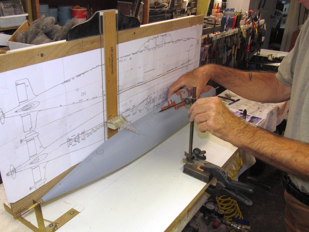
    upgrading the SSY 1/96 ALFA kit - Page 2 08iKFa

    I mocked up the bow plane arrangement. As is my want, I endeavor to make the bow/sail planes on my r/c submarines practical. Such is the case with this little 1/96 ALFA class submarine. A unique feature of this class of submarine was the height stagger between the two planes (to obtain the internal clearance of the retract mechanism when the planes are housed in the ‘retracted’ position). A unique feature, I wanted to show-case; a little chaos is a good thing every now and then.

    upgrading the SSY 1/96 ALFA kit - Page 2 QyVq3H

    An example of intentional asymmetry on the ALFA design is the vertically displaced distancing of the two bow planes. Note how they are staggered in relation to each other. As these retractable control surfaces slide in and out from the ‘retracted’ and ‘deployed’ positions there was not enough space between them, when retracted, to position them on the same vertical plane. Malachite’s solution was to stagger them (one above the other) to get these long-of-span control surfaces to fully retract when stowed.

    I assume that the bow planes were only rigged out when operating at periscope depth or during evasive maneuvers where rapid depth change rates were required. Otherwise, these dragy control surfaces would have been neatly tucked into the hull. After all, the ALFA’s were the Soviet’s second fastest combatant type submarine ever in service, so everything that could be done to make these boats ‘slick’ was done. You don’t need bow planes when you’re booking along on a flank bell at transit depth.
    upgrading the SSY 1/96 ALFA kit - Page 2 CdfUzu

    Because the two control surfaces don’t share the same plane, I cannot use a single operating shaft between the two bow planes. I’ll have to provide each with its own bearing tube within the hull and interconnect the two operating shafts (one per plane) with a flexible coupler, likely a short length of flexible rubber tubing – an arrangement that will permit both planes to rotate in unison off of one bell-crank.

    To insure that the internal bow plane operating shaft bearing tubes are positioned parallel with one another I’ve extended a temporary operating shaft through the hull with a bit of it projecting through the opposing side of the hull. Later, these extended, temporary operating shafts will jig the bearing tubes in correct position as I epoxy them within the hull.
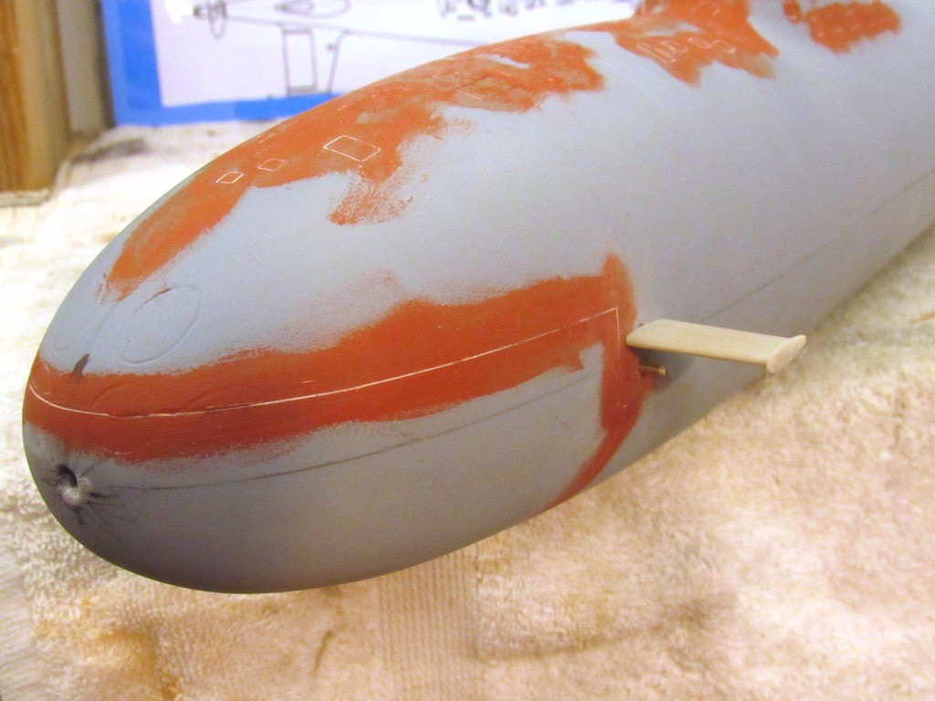
    upgrading the SSY 1/96 ALFA kit - Page 2 AoOSDv

    The escape buoy sits in a well. I turned a well from some RenShape and CA’ed it into a hole I punched atop the hull, just aft of the sail.

    I could have elected to simply scribe a circle to represent the demarcation between circular buoy and deck, but I’ve been giving some thought of making a practical buoy – as advocated by Manfred Reusing who has been outfitting his scale r/c submarines with such a sub-system for decades -- never hurts to have a back-up to get a disabled, sunken model submarine back to the surface!

    A possibility, later, taking Manfred’s lead, is to outfit the model with a practical float that would be tethered to the model through a long fishing-line down-haul cable. The buoy released to rise to the surface once a water-soluble retainer had been exposed to water for a significant amount of time (a piece of spaghetti or a Tic-Tac).
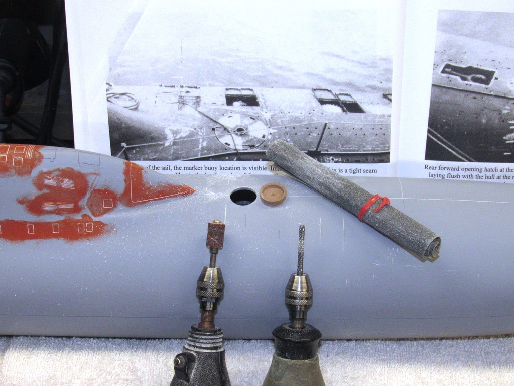
    upgrading the SSY 1/96 ALFA kit - Page 2 NNDJVF

    There were only three significant errors I’ve found on the hull: the Sail is too short (but to be honest, this model might be representing the prototype which reportedly had a sail of different contours than the production boats); the torpedo tube shutter doors are to low and too large of diameter; and the location of the after escape trunk hatch flat is too far aft.

    Here I’ve – for the sake of illustration – only worked one-half of the after escape trunk hatch flat. First I used a course file to shave down the after flat (the bare GRP exposed) to the normal contour of the hull, and used CA and baking soda to build up a mass forward (where the penciled hash-marks is) that is then filed to a new flat. The port side eventually got the same treatment.
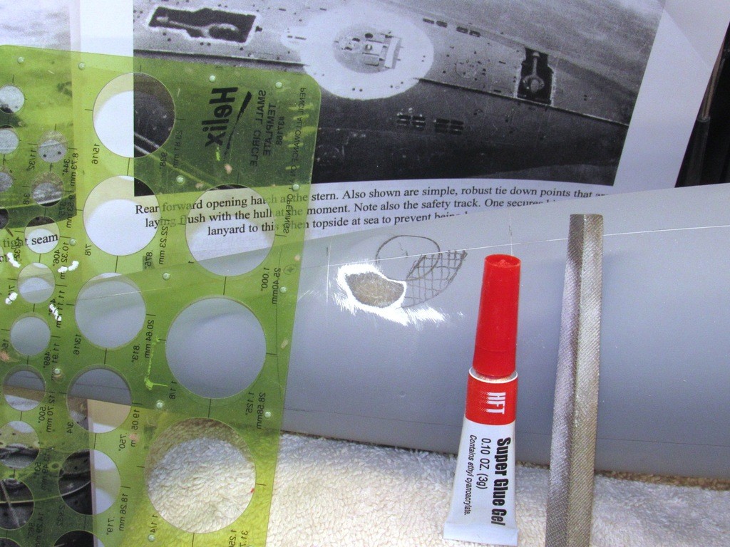
    upgrading the SSY 1/96 ALFA kit - Page 2 NC3bQO

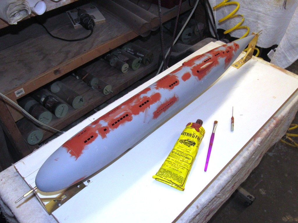
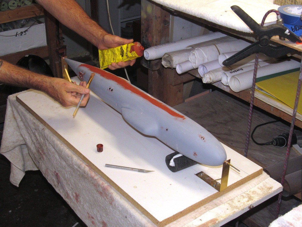
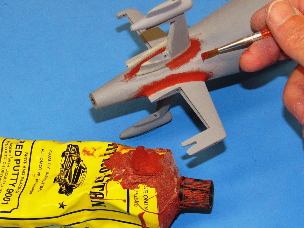
    After scribing in the deck and sail details I applied touch-up putty to fill datum lines, cheat-lines, and flawed engraving work. The putty was pushed into the work with a finger, after which I quickly chased out the still wet putty from the engraved items I wanted to retain with the finishing scribe.
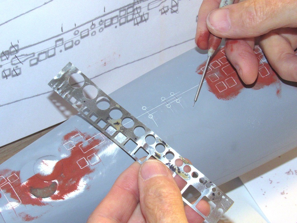
    upgrading the SSY 1/96 ALFA kit - Page 2 E3unSu

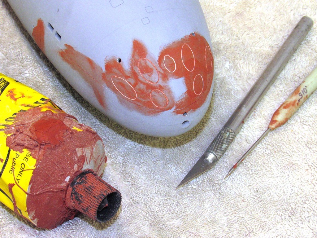
    The thinly applied putty dries quickly, and those areas were wet-sanded with #600 backed by a semi-stiff sanding block. You can make how the red colored filler fills the flaws.

    upgrading the SSY 1/96 ALFA kit - Page 2 VIjYiz

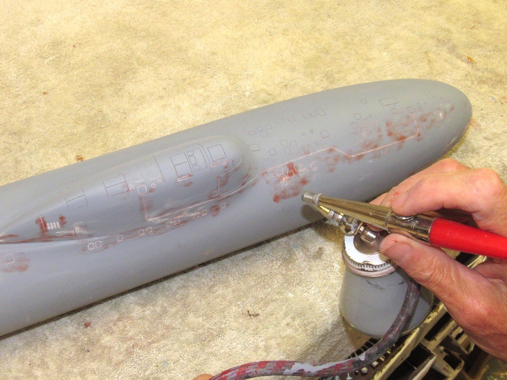
    I’ve already laid down primer to the port side, and you can just make out some of the engraved items. The starboard side is about to get its coat of primer.

    Unaddressed flaws, missed or inadequately filled by the putty, are revealed by the gray primer. Such problem areas were addressed with further scribing and/or putty to put the work right, followed by a touch-up blast of primer. This process repeated till things are near perfect.

    upgrading the SSY 1/96 ALFA kit - Page 2 2zOt8m


    merriman
    merriman
    Guest


    Posts : 347
    Join date : 2011-10-16
    Age : 75
    Location : Virginia Beach, Virginia

    upgrading the SSY 1/96 ALFA kit - Page 2 Empty Re: upgrading the SSY 1/96 ALFA kit

    Post  merriman Thu Sep 26, 2019 11:10 pm

    With the majority of limber and flood-drain hole locations marked off onto the hull questions remained as to specific location and size of some.

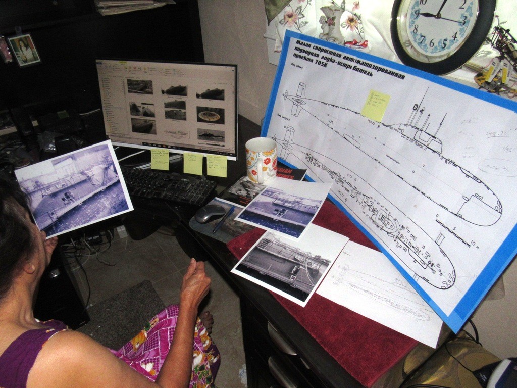
    The plans are authoritative, as just about every photos of an actual prototype confirmed what was depicted on the drawing. However, there’s always items that need a better look at before building a part or engraving a line. It’s on those occasions that I drag the drawings and folders into the office, get into my computer folders dealing with the subject, and do a deep dive into the specifics in question.

    Ellie and I gave things a close look-see, bouncing our attention between computer screen, photos, and the plans to skull things out as best we could. Once we concurred the plans were annotated accordingly, and I tucked my documents under an arm and trudged back to the man-cave to work the magic.

    upgrading the SSY 1/96 ALFA kit - Page 2 UpK6hE

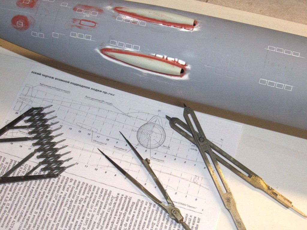
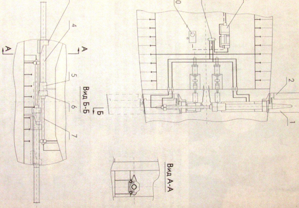
    One area I wanted to get right was the exact position of the two secondary loop condenser intake scoops. In my folder I found this excellent drawing that had the look of a source document, permitting me to trust it enough to loft off the position of the scoops onto the bottom of the hull. Translating the small drawing to the size of the model was accomplished with the aid of proportional dividers.

    upgrading the SSY 1/96 ALFA kit - Page 2 32YIKy

    The two resin scoops were degreased, and conformably sanded to match the compound curve of the hull where they would be attached. First their outlines were scribed onto the hull so I could match an oblong hole in the hull with the ‘intake’ opening ground at the front of each scoop piece. Each scoop was then secured in place with plenty of CA and CA accelerator liquid.

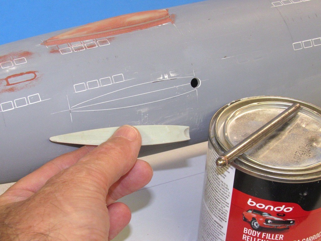
    Not indicated on the drawing, but revealed in our study of prototype photos of boats in drydock, is a rather large radius fillet between the scoops and the hull. I scaled that radius to the model and selected a dapping tool of appropriate diameter, using it later to screed Bondo automotive filler at the union between scoops and hull, producing the fillet that so neatly blends these structures into one.

    upgrading the SSY 1/96 ALFA kit - Page 2 YAukLs

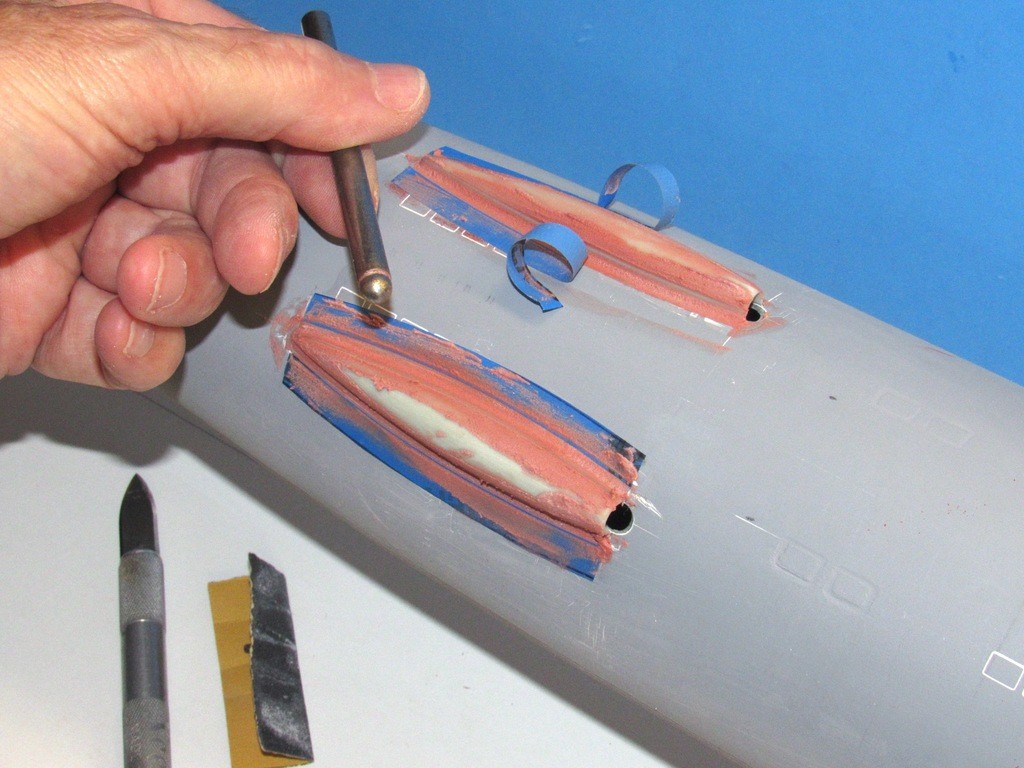
    Masking tape was used to minimize the mess of excess Bondo getting onto areas of the hull I don’t want it. You see here how the dapping tool – in this application, more of a wax melting radius tool – is used to produce a constant radius fillet between scoops and hull.

    upgrading the SSY 1/96 ALFA kit - Page 2 7UJUwL

    After the Bondo fillets had hardened enough I used specialized round-files to refine the fillets and give their surface a roughness that would enhance the adhesion of the later applied touch-up putty. The files were used wet to avoid excessive grit between the teeth. The Bondo that got onto the scoops was abraded off with double-sided sanding tools used wet.

    There is a slight radius either side of the intake hole. These sharp, little fillets were formed by CA mixed with baking soda and filed to shape with purpose made riffler files.

    upgrading the SSY 1/96 ALFA kit - Page 2 KadSHU

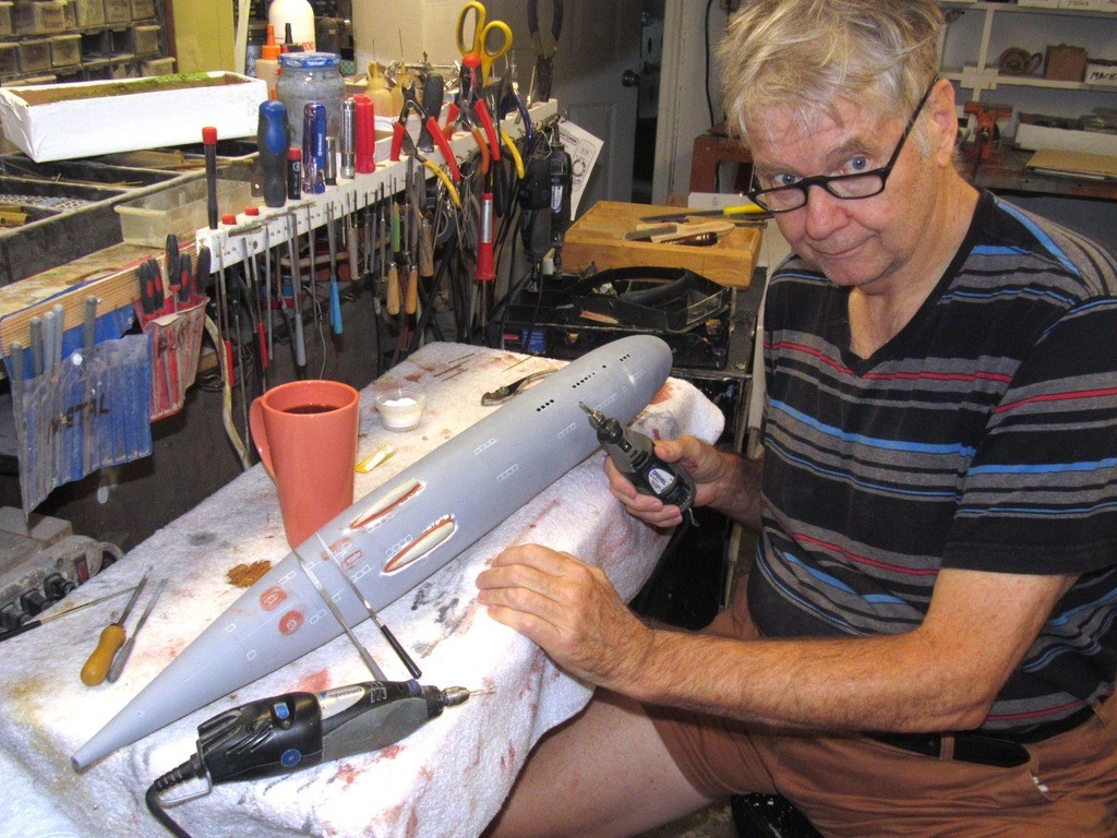
    I’m hovering over one of the three ‘mobile’ work stations in my shop. These are modified old-style hospital tables, adjustable in height and supported over caster wheels. This type table permits me to adjust the height of the work to suite specific postures I need to assume, standing, sitting, or hunched over. When required these mobile tables can be ganged together for long work; and their particle board tops permit me to quickly build onto the table itself jigs or fixtures needed hold or align the work. They’ve been an important furnishing in this shop for decades.

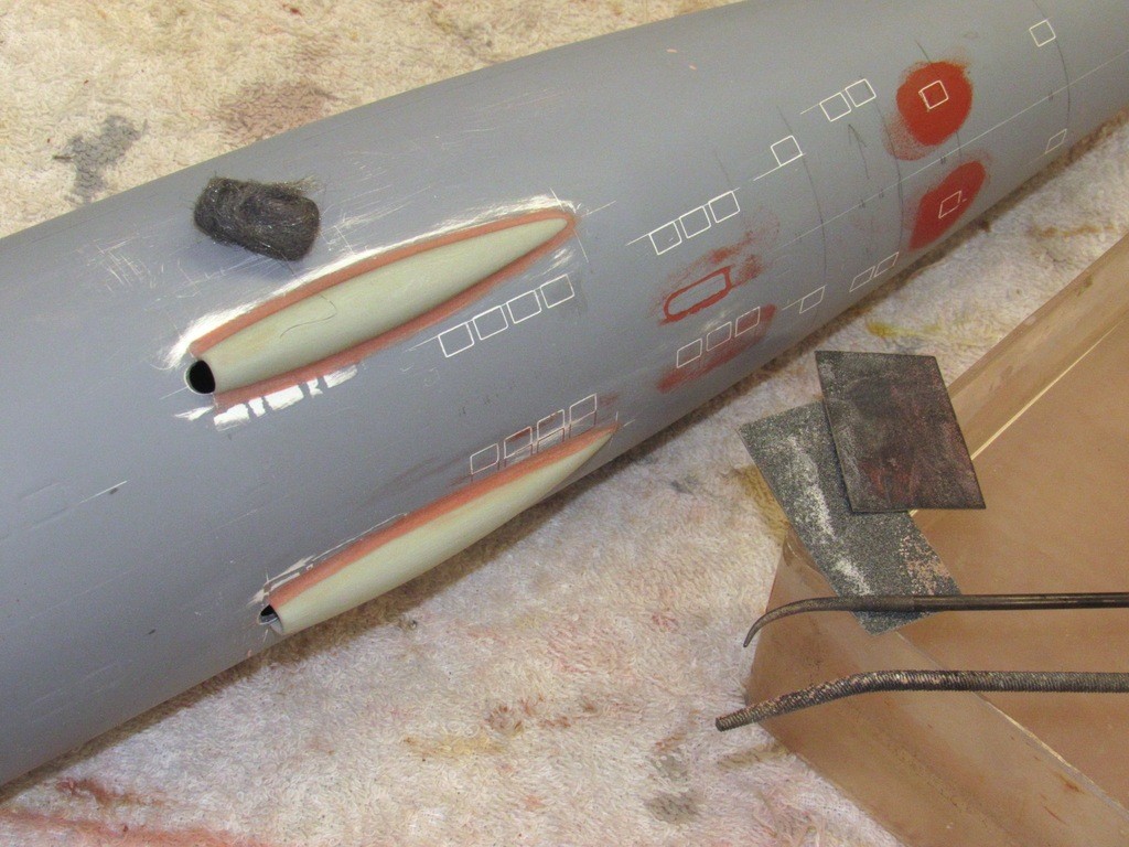
    Here I’m in the process of boring out the flood-drain holes into the bottom of the ALFA’s hull.

    upgrading the SSY 1/96 ALFA kit - Page 2 Rqwdlm

    I found that the task of opening up holes in GRP substrates is best done with a variety of rotary bits followed by precision shaping with the aid of various small files.

    Location and shape of each hole is defined by an engraved line scribed into the hull. The initial penetration is done with a rough burr, and then the hole is roughed to shape with a suitable diameter drill bit, used as an end-mill. Once the hole approaches the scribed outlines of the eventual shape I switch to files. I make no effort to maintain a radius at the square hole edges, that refinement later achieved with putty.

    The four holes at the bottom illustrate the three stages I’ve just described. At the left I’ve started to dig into the glass with the burr; the hole to the right of that has been opened up as much as possible with the burr; the hole second from the right has been refined with a 1/16” drill bit used as a hand-held end-mill; and the hole to the extreme right has been worked to the engraved outline with jeweler’s files.

    upgrading the SSY 1/96 ALFA kit - Page 2 IKyFQ7

    Time has come to start integrating more of the cast resin parts on and within the hull.

    ‘Capture lips’ have already been installed within the upper hull – these work to hold the raised longitudinal flange of the lower hull up tight against the inside edge of the upper hull, insuring registration between the edges of the upper and lower hull.

    The two semi-circular SubDriver cylinder foundations and Velcro-indexing pin foundation will now be secured into the lower hull with the aid of 4-40 machine screws. And the forward propeller shaft bearing foundation will be sized and centered into the tail-cone, but not yet permanently installed – and it won’t be permanently installed till I’ve worked out a successful linkage for the rudders and stern planes.

    Next on my to-do list is manufacture and installation of the two operating shaft bearings for the bow planes.

    upgrading the SSY 1/96 ALFA kit - Page 2 10VsL0

    Giving me a bit more room on the marking jig was removal of the no longer needed plan bill-board. The jig is now used to hold the work and rotate it as I go about the laborious task of applying touch-up putty and later wet-sanding it off.

    upgrading the SSY 1/96 ALFA kit - Page 2 O2wtpb

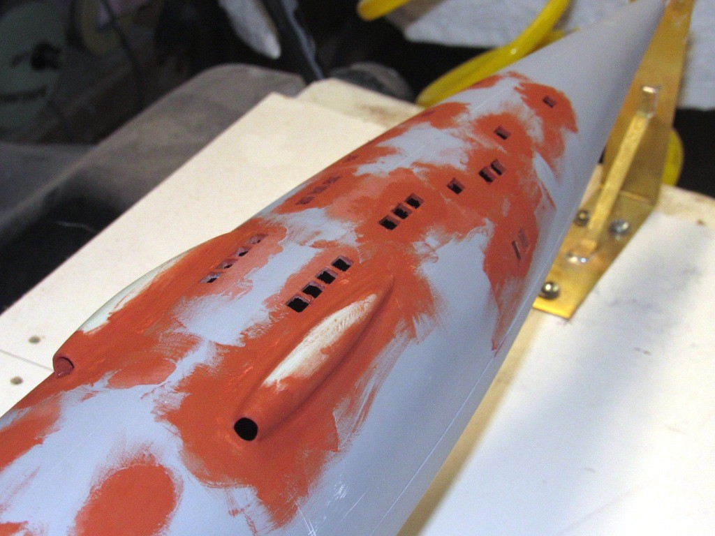
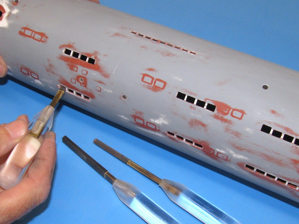
    After all that work grinding open the limber and flood-drain holes I coated the work with Nitro-Stan and pushed the putty into the inside edges of the square holes with a 1/16” diameter brass dowel. This does two things: swirling dowel around on the inside edges of the holes pushed the putty into the edges, filling tool-marks; and the round tool produced fillets at the four corners of each hole, more accurately capturing the shape of these openings at the bottom of the hull.

    upgrading the SSY 1/96 ALFA kit - Page 2 D77vCq


    merriman
    merriman
    Guest


    Posts : 347
    Join date : 2011-10-16
    Age : 75
    Location : Virginia Beach, Virginia

    upgrading the SSY 1/96 ALFA kit - Page 2 Empty Re: upgrading the SSY 1/96 ALFA kit

    Post  merriman Sat Sep 28, 2019 3:38 am


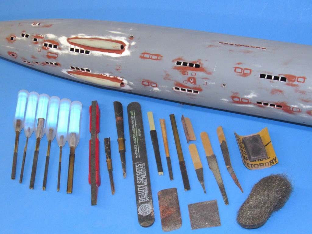
    An often unappreciated aspect of fine model-building is the design, manufacture, selection, and use of abrasive type tools. Files, sandpaper, grinding discs, saw blades, abrasive pads and steel-wool, all are examples of reduction tools that chip away at the work – abrasive tools. Below is a small selection of the abrasion tools used, or could have been used, on the 1/96 ALFA project.
    A competent model-builder knows what type of tool to use, where to use, how to use it, and (of course) have that tool at hand.

    The only tools made specifically for this job – and will find use on later jobs as they join the others in my collection – are the six specialized sanding tools to the left. All used to refine the shape of the many different sized limber, intake, discharge, and flood-drain holes of this subject.
    upgrading the SSY 1/96 ALFA kit - Page 2 QkuGPC

    Specialized sanding tool, each dealing with a specific hole size and geometry, each equipped with a #400 grit sandpaper wrapped brass mandrel. K&S brass U-channel and square section tubes were used as the mandrels.
    The clear handles are length of Acrylic rod that were tapered and bored on the lathe, the bore slightly smaller than the brass mandrel it accommodates. Securing a mandrel to a handle was done by heating the brass mandrel, then jamming it into the handle. As the acrylic melted, the mandrel was pushed into the undersized hole. Once cool mandrel and handle were one -- no glue required.

    The original engravings on the hull, for the most part, did not jive with my documents, so that work was filled. You can make out some of the original engraving in red (filler).

    upgrading the SSY 1/96 ALFA kit - Page 2 7qnof8

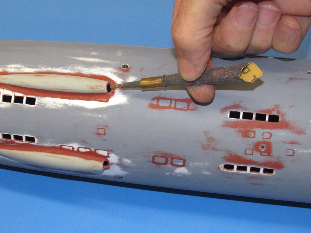
    I twist sandpaper into a tapered, round sanding tool. Note how a length of brass tube, belled at one end, is used to girdle and keep tight the wound piece of sandpaper. One of these tools is being used here to clean up the inside of the scoop intakes.

    upgrading the SSY 1/96 ALFA kit - Page 2 FVHVfN

    The job of applying touch-up putty continued, but the task made easy using the marking jig to hold the work steady – note the crutch under the hull that keeps it from rotating as I brush on the putty.

    In this case I’m evening up a slight disparity of height between the upper hull and lower hull longitudinal edges. As the wet putty gets into the seam between the two halves it had to be chased out before drying. A knife-point was used to break the putty bridge between the two halves.

    upgrading the SSY 1/96 ALFA kit - Page 2 SDuEIG

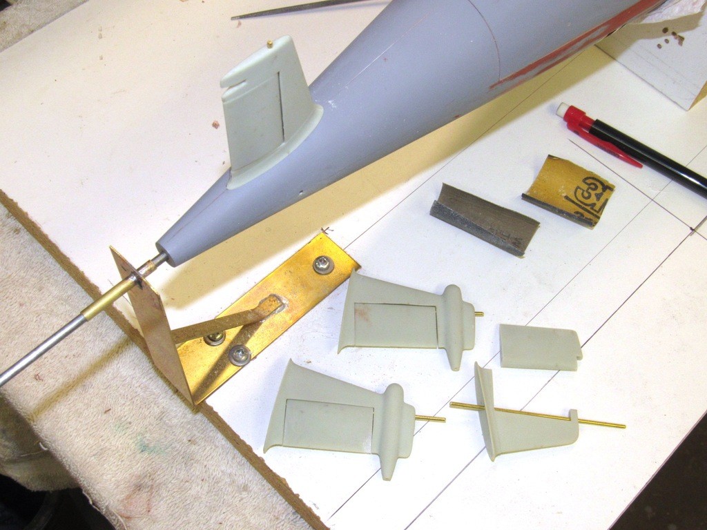
    The fit between control surfaces and stabilizers was checked for non-binding movement. That accomplished I checked the fit and alignment of each stabilizer to its eventual location at the stern of the hull.
    upgrading the SSY 1/96 ALFA kit - Page 2 EarSTs

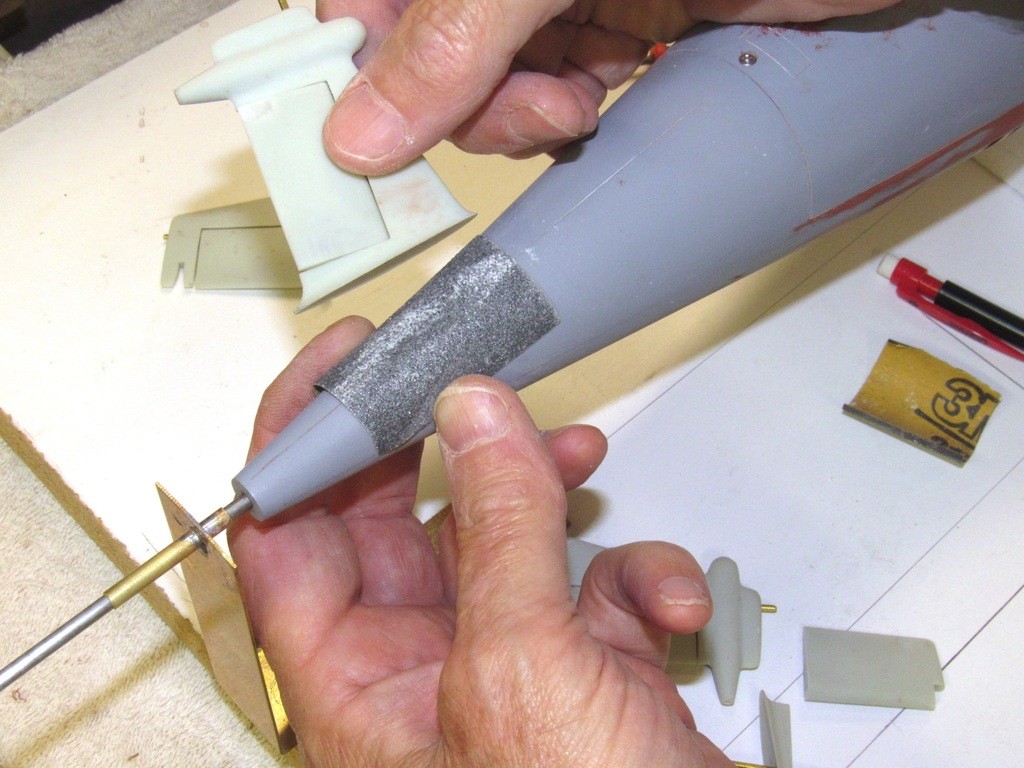
    I’m performing a bit of touch-up conformal sanding to the stabilizer roots. The objective here was to get each stabilizer to line up on the hull with its trailing edge perpendicular to the jigs bed and its cord in line with the profile plane of the hull.

    The conformal sanding was done with a light touch: sand a bit; check alignment; sand; and check again. Only after each stabilizer sat, unsupported atop the stern, its trailing edge and cord falling along the perpendicular and profile planes, would it be put aside and the next stabilizers root given this final contouring.

    upgrading the SSY 1/96 ALFA kit - Page 2 EYOk56

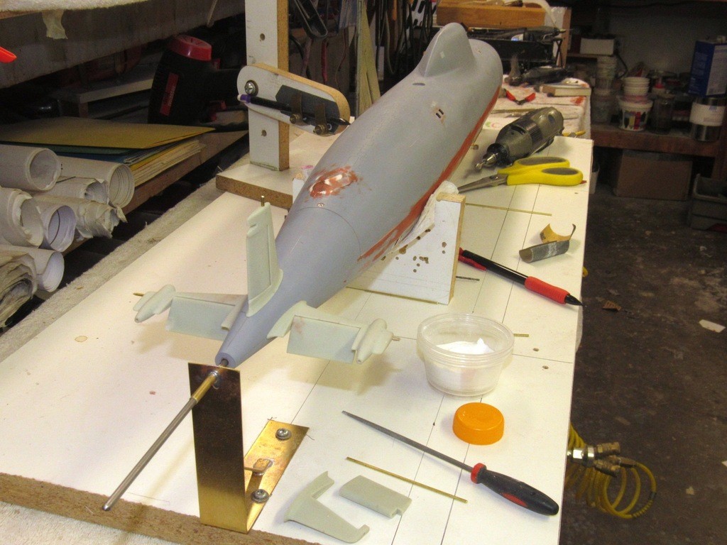
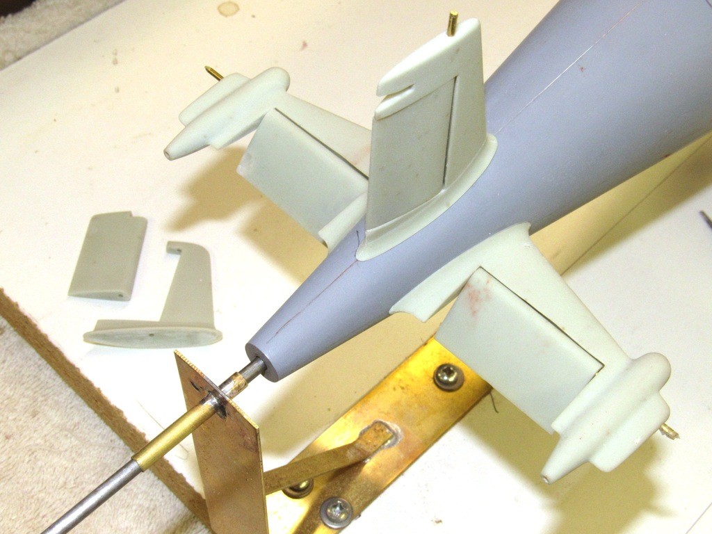
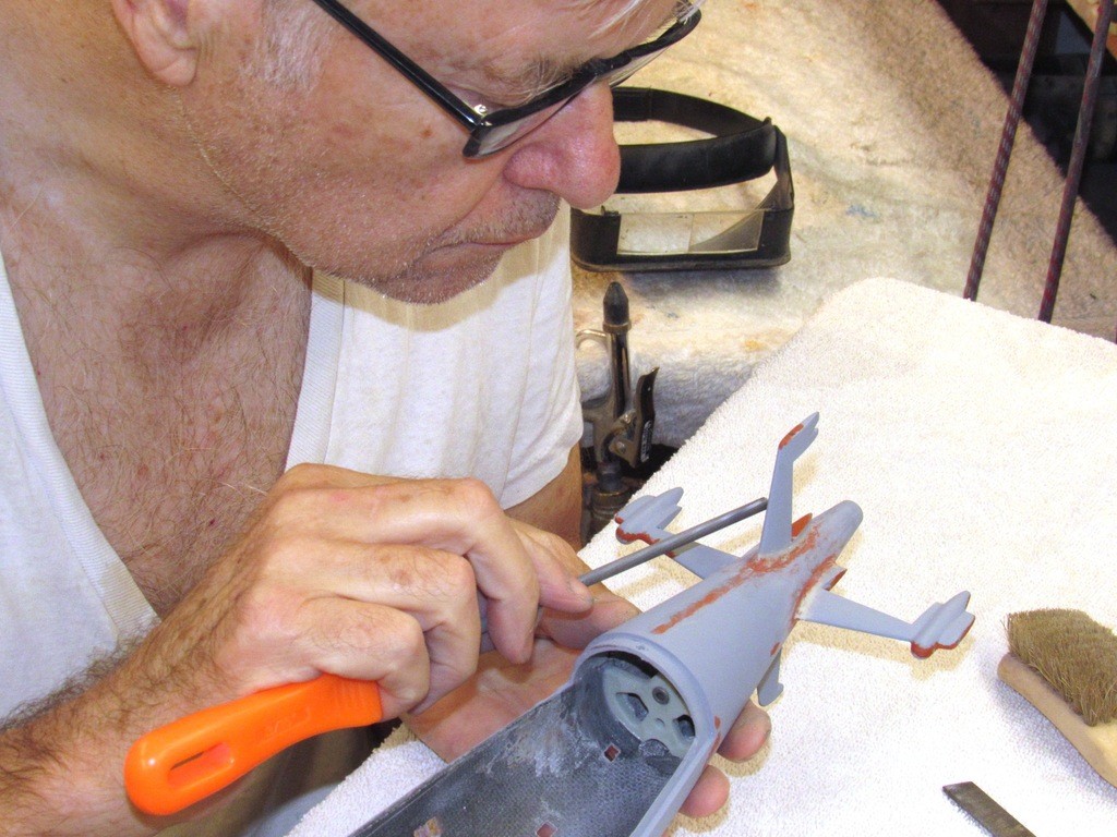
    Alignment of the stabilizers to the hull was assured by running a 1/16” brass rod through opposing stabilizers and hull. Checking that the holes through which the brass rods ran were properly distributed, a Machinist’s surface-gauge and right-angle triangles were used as well. Again, the marking jig was a useful tool as I went about this task of mocking-up the assembly of the stabilizers to the hull.

    upgrading the SSY 1/96 ALFA kit - Page 2 Qr7szh

    The space within the tail cone where the control surface linkages terminate is very, very tight. So, I do not yet permanently glue the stabilizer to the hull. Just a mock-up test fit. I still have much grinding on the tail-cone interior and don’t want the delicate stabilizers glued back there yet – just too easy to break them off during such handling.

    upgrading the SSY 1/96 ALFA kit - Page 2 UQ4TBc

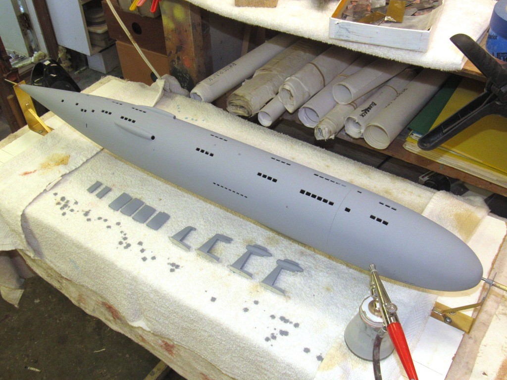
    Here I’m applying another coat of primer to find flaws not yet evident. First, at moderate pressure and the paint-flow dialed back a bit, I hit the areas that either are red touch-up putty or white gel-coat with spot applications. I then turn up the pressure to #11 and set the paint-flow to ‘kill’ and clobbered the entire model with a thick primer coat.

    upgrading the SSY 1/96 ALFA kit - Page 2 IkCAhs

    After the work had dried overnight I inspect the gray surface for flaws and addressed them with a sanding tool or more touch-up putty.

    upgrading the SSY 1/96 ALFA kit - Page 2 TiIOry


    salmon
    salmon
    AMS Forum Owner


    Posts : 312
    Join date : 2011-09-02
    Age : 64
    Location : Las Vegas, Nevada - USA

    upgrading the SSY 1/96 ALFA kit - Page 2 Empty Re: upgrading the SSY 1/96 ALFA kit

    Post  salmon Sat Sep 28, 2019 4:32 pm

    Wow, simply wow!
    merriman
    merriman
    Guest


    Posts : 347
    Join date : 2011-10-16
    Age : 75
    Location : Virginia Beach, Virginia

    upgrading the SSY 1/96 ALFA kit - Page 2 Empty Re: upgrading the SSY 1/96 ALFA kit

    Post  merriman Sun Sep 29, 2019 7:09 pm

    I’ve learned to keep as many items that make up a model removable for as long into the building process as possible. Fit and operability of the parts often does not go as planned and the ability to remove a part, or assembly, to perform a modification saves much time and aggravation. That guiding principle on display here: deferring permanent installation of stabilizers, SubDriver foundations, control surface linkages, and running gear. Such items permanently installed only after the entire system has demonstrated correct operation without anything getting in the way of the other.

    Even after the stabilizers are bonded to the hull I retain the ability to easily remove the operating shafts, control surfaces, and linkage elements for repair or adjustment; as is the case with the propeller, propeller shaft, and bearings – they all can be removed without damage.

    I design for scale-like appearance, performance; and easy access to all moving parts.

    upgrading the SSY 1/96 ALFA kit - Page 2 X3AHZk

    The initial fit of the stern control surface operating shaft bell-cranks revealed a lot of interference between the inside of the stern and the bell-cranks. I found the most effective way of digging away some of the GRP was with this little pneumatic rotary grinder equipped with a Carbide ball-burr. The small diameter grinder permitted me to still eye-ball the work as I carefully ground away material from within the tapered stern. A most useful tool.

    upgrading the SSY 1/96 ALFA kit - Page 2 Y0O82Z

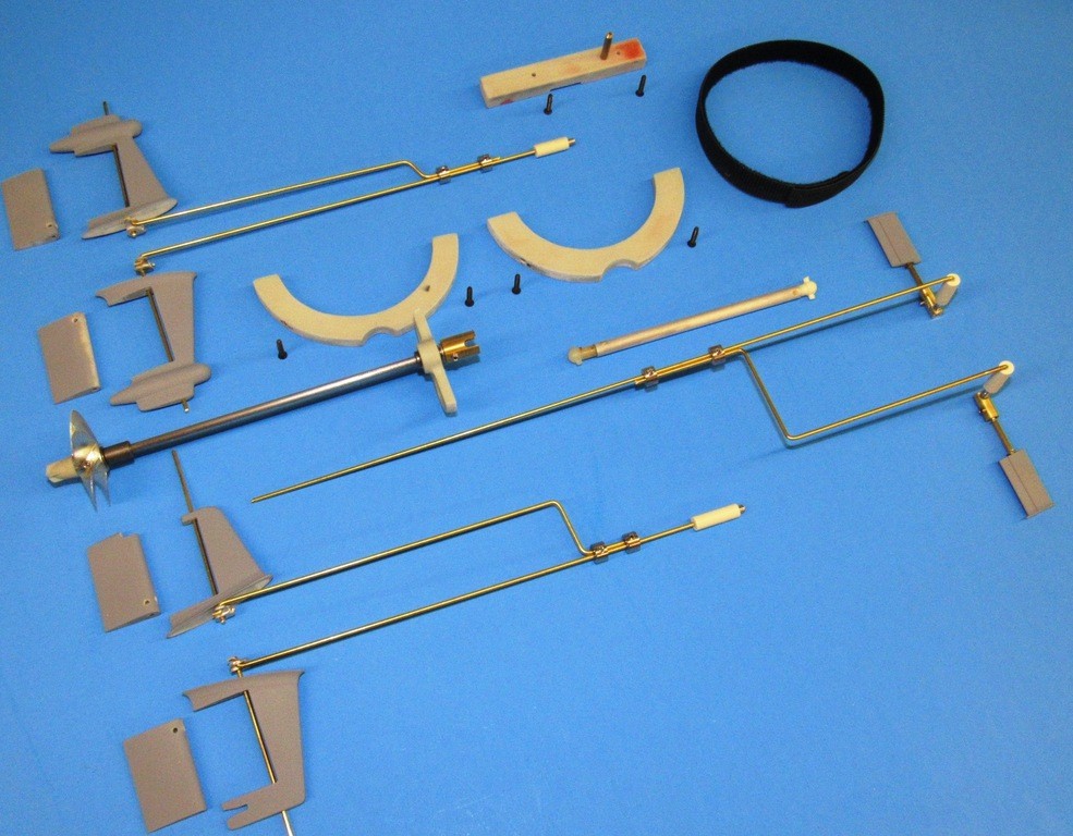
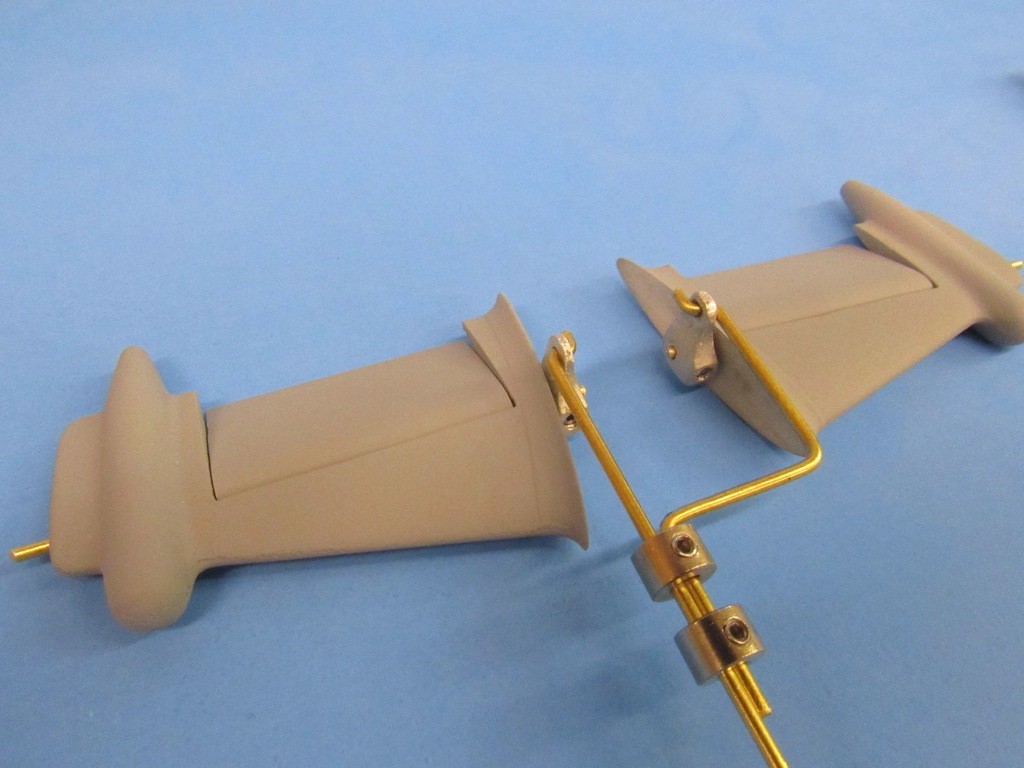
    At the start of this project I had hoped to use at least one interconnecting yoke between opposed control surface operating shafts in the stern. But, as it turned out, things are just too tight back there to permit that. So, I had to employ discrete bell-cranks for all four operating shafts, which of course meant a dedicated pushrod for each bell-crank. Note how the two pushrods operate as one by ganging them together with wheel-collars.

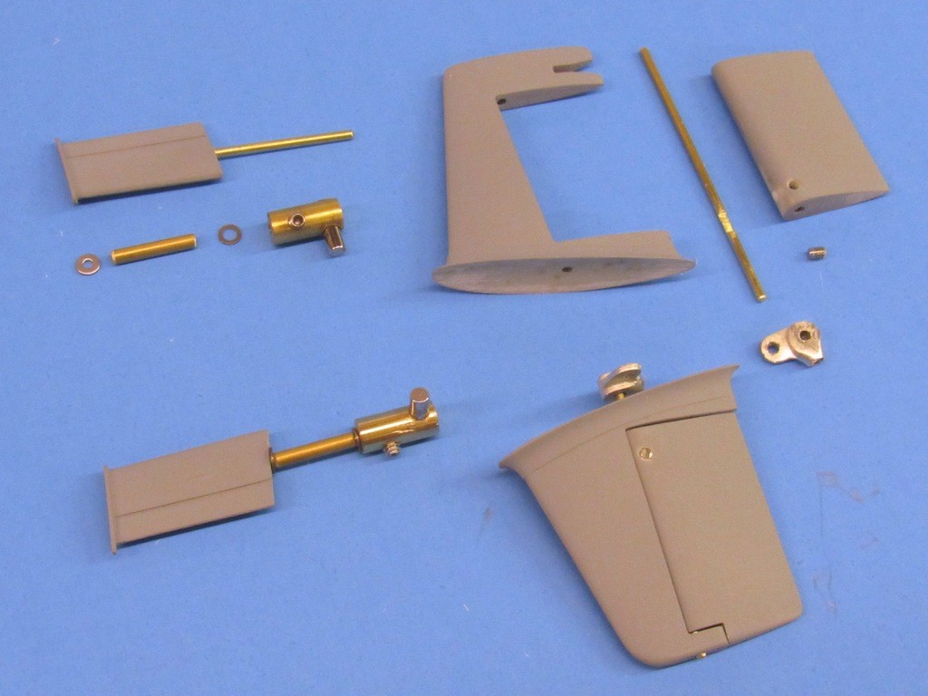
    The cast white-metal bell-cranks are of my own manufacture – just one of many sizes and styles I have in the spares boxes that litter the walls of my shop. The pushrods secure to the bell-crank with a classic Z-bend, and the bell-crank made fast to the operating shaft with a set-screw.

    upgrading the SSY 1/96 ALFA kit - Page 2 Y3LvEX

    A 2.5” diameter SubDriver, with suitably sized ballast tank, will provide the control, propulsion, and ballasting tasks for this model. Here I’m checking out the interface between the SD’s propulsion and control outputs.

    While investigating the best way to get the bell-cranks situated in the stern I eventually settled on this arrangement of pushrods – a pair for the stern planes, and a pair for the rudders. The SD pushrod atop the cylinder will eventually make up to the bow plane pushrod. There will be five channels of operation for this model: Rudder, stern planes, bow planes, ballast, and throttle. Additionally there will be autonomous control of the stern planes and bow planes by on-board angle and depth sensors.

    upgrading the SSY 1/96 ALFA kit - Page 2 G8K5KJ

    As is my practice the control surface pushrods make up to the SubDrivers pushrods through magnetic couplers – a concept I appropriated decades ago from the always inventive, Brian Starkes.

    Note the large diameter aluminum intermediate drive shaft under the pushrods, interface between SubDriver motor output and propeller shaft. Dumas dog-bones and couplers make up quick connect/disconnect unions between intermediate drive shaft, SubDriver, and propeller shaft.

    upgrading the SSY 1/96 ALFA kit - Page 2 KcQ9kb

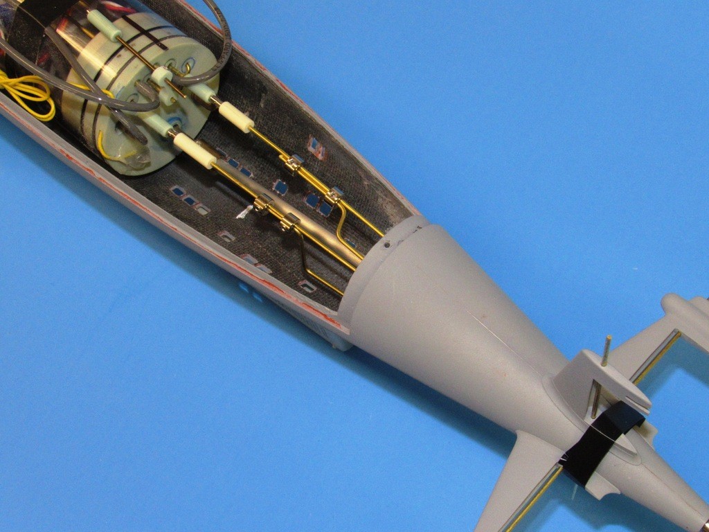
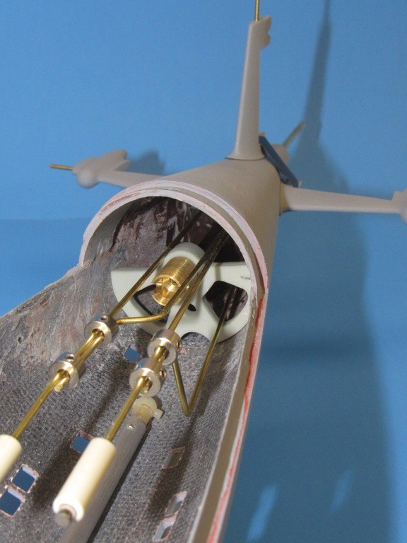
    You see how tight things get at the tapered stern of the 1/96 ALFA. It took much fiddling to work out how the pushrods ran back there so as to prevent binding or interference between them. Note how the pushrods run over and even through the cast resin forward propeller shaft bearing foundation.

    upgrading the SSY 1/96 ALFA kit - Page 2 96hrX5

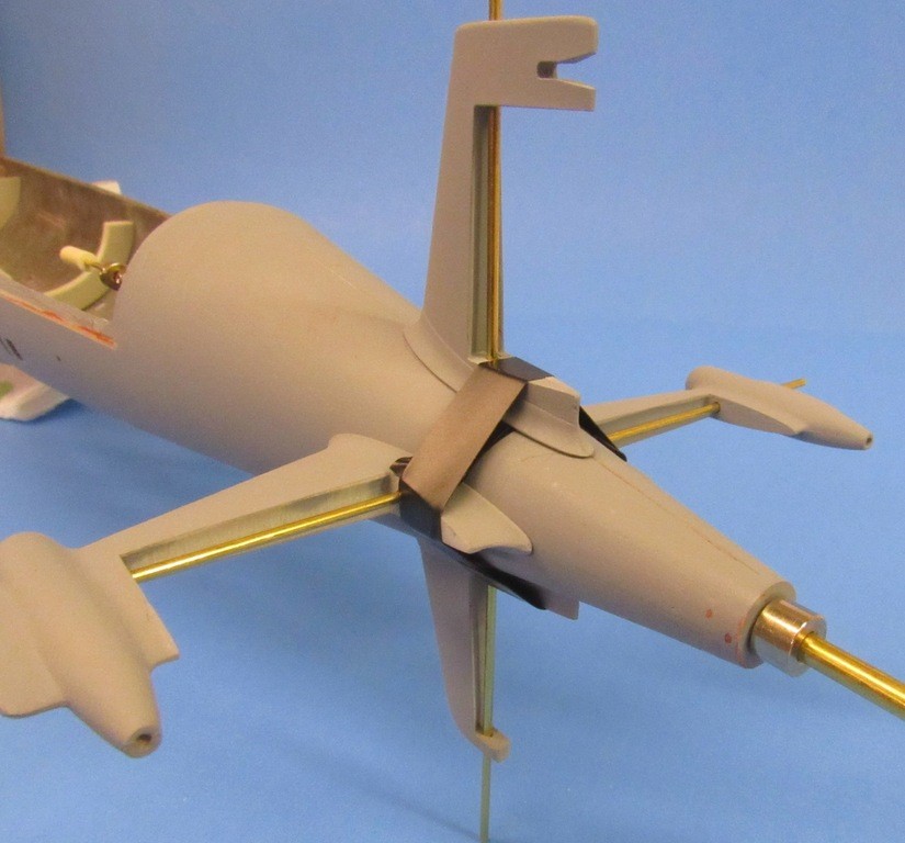
    Note that the horizontal and vertical stabilizers have temporarily been secured to the hull with Electrician’s tape. The stabilizers were kept off-model as long as possible to avoid damaging them as the model is handled as other operations are performed. They’re installed here to serve as alignment bearings for the control surfaces (not installed for this operation) operating shafts. At this point I’m test fitting the four bell-cranks to the internal terminus of each operating shaft, checking for clearance of the bell-cranks from the inside surfaces of the hull as well as assuring non-interference between the bell-cranks themselves, and centrally running propeller shaft.

    A 1/8” brass rod is a stand-in for the propeller shaft as I center the forward propeller shaft bearing foundation into where it will eventually be bonded within the hull.

    upgrading the SSY 1/96 ALFA kit - Page 2 59SXXZ

    Initially I planned on interconnecting the slightly off-set bow plan operating shafts with a flexible length of surgical tubing between the two. Though practical, that arrangement would have been difficult to set-up and adjust in the tight confines of the bow.

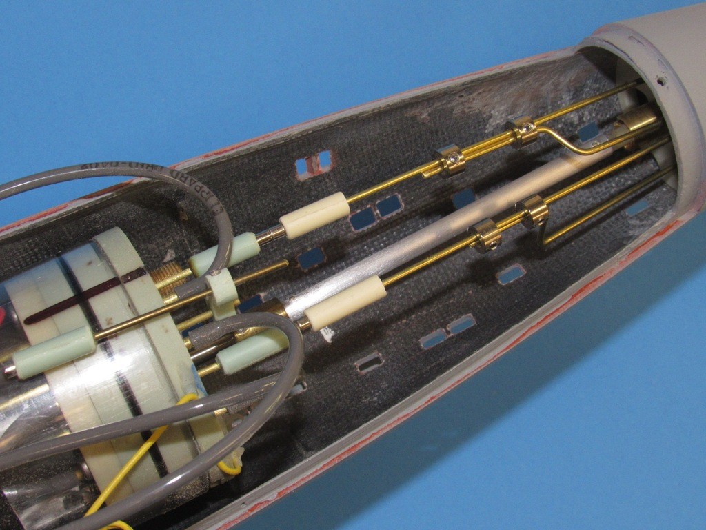
    Instead, I went with this solution: magnetic couplers. This arrangement is much easier to set-up and install/remove. With this linkage there is near-zero back-lash; the magnets present enough force to move the control surfaces without slippage; but do not hold with a force strong enough to damage the linkage should the planes be subject to collision or rough handling – in those circumstances the magnetic union will pull apart, but will rejoin automatically once the unwanted force is removed. Pretty slick!

    upgrading the SSY 1/96 ALFA kit - Page 2 EhiKZc

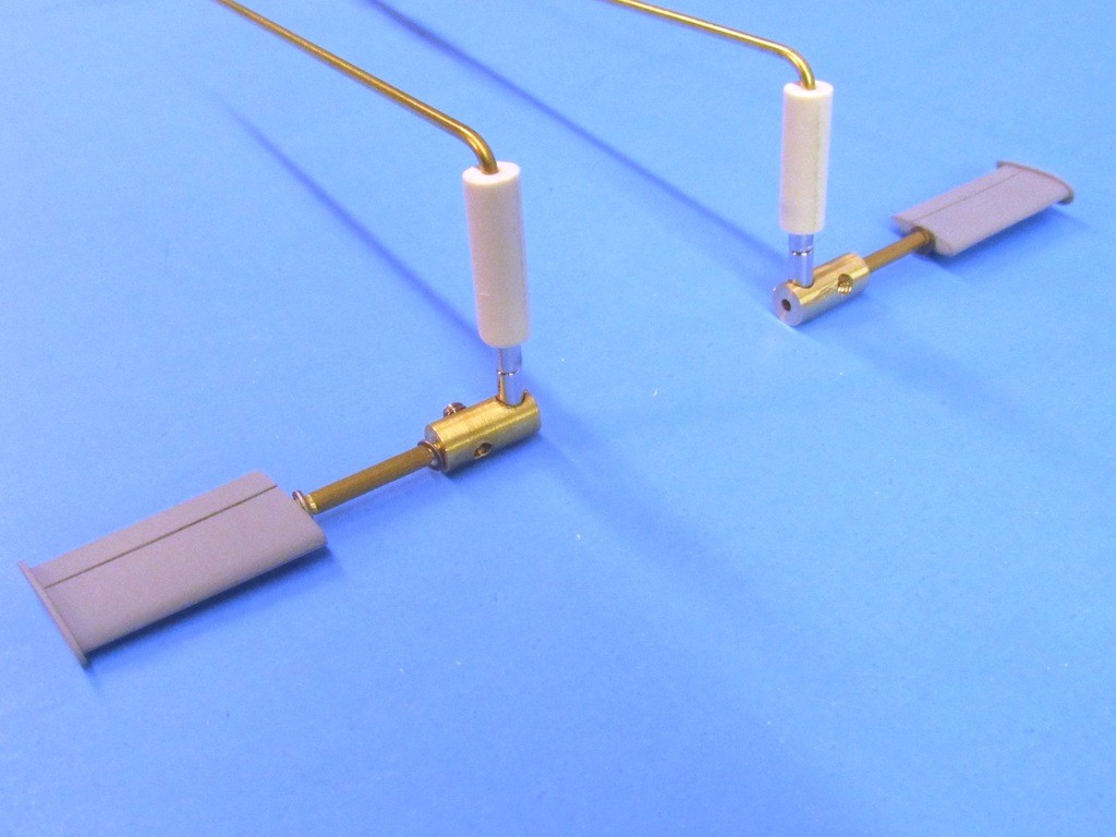
    Not applicable to this model, but I found that it might be possible to use the magnet attachment points as the center of rotation for bow planes that retracted by swinging in and out – this would be useful for practical retracting bow planes such as employed by NOVEMBER, HOTEL, ECHO, SIERRA, FOXTROT, KILO, and TYPHOON class submarine models. Just for fun, I demonstrate that capability on this set of ALFA bow planes.

    upgrading the SSY 1/96 ALFA kit - Page 2 M63U7d

    Each bow planes operating shaft rotates within a short length of brass tube, that bearing tube glued within the bow. A short length of the operating shaft extends into the hull and makes up to a magnet equipped bell-crank. A set-screw secures the bell-crank to the operating shaft. The press-fit magnet is influenced by a magnet attached to the forward end of the bow plane pushrod.

    Each of the stern control surfaces was made fast to its operating shaft through a small set-screw. The operating shaft makes up to its bell-crank and also is held in alignment by the stabilizer outboard and root bearing holes.

    upgrading the SSY 1/96 ALFA kit - Page 2 9dJSNW


    merriman
    merriman
    Guest


    Posts : 347
    Join date : 2011-10-16
    Age : 75
    Location : Virginia Beach, Virginia

    upgrading the SSY 1/96 ALFA kit - Page 2 Empty Re: upgrading the SSY 1/96 ALFA kit

    Post  merriman Tue Oct 01, 2019 11:42 am


    This’ll be the last WIP on this topic for a few weeks: I’m dedicating the next ten days to getting my 1/96 r/c submarine fleet ready for the big North Carolina ‘fleet-run’ event this October 11-12. I’ll rejoin this project mid-October. The fleet-run at City Lake is the last big event of the year for me. After a few days of post-operation maintenance and some decompression time, it’s back to the salt-mine and production work for the Nautilus Drydocks. Bob has some tooling jobs and a new SD design he wants worked up before year’s end. It’s good to be employed!!

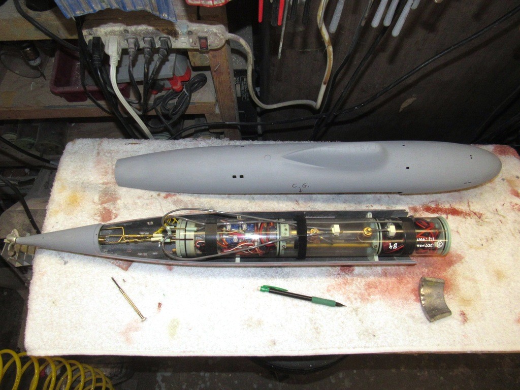
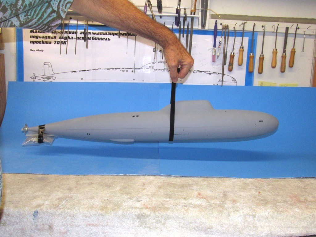
    After checking the fit and function of all the internal hardware the time had come to establish where in the lower hull to place the fixed lead weight in order to position the model submarines center of mass (center of gravity for you old-school types) so that the model balanced at, or slightly aft of, the center of the SubDrivers ballast tank. That ballast tank, slightly forward of the submarines longitudinal center -- the desired location of the center of gravity annotated on the hull with a pencil marked, ‘C.G.’

    upgrading the SSY 1/96 ALFA kit - Page 2 FlVUB0

    This determination -- where to permanently mount the fixed ballast weight -- made after installing (or in the case of the stern stabilizers and control surfaces, ‘hanging’) all items in their correct locations within or upon the hull. Finding the c.g. was best done using a sling of Velcro as a suspension fulcrum as I experimented with the weight, moving it back and forth until I found a position in the forward hull where the weight placed the models c.g. where I wanted it.

    upgrading the SSY 1/96 ALFA kit - Page 2 GIZdC1

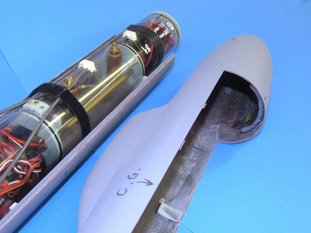
    The single Lead weight, like the resin foundations, was initially held in place with machine screws. Here, 2-56 X 3/8” flat-head screws. The holes drilled through the bottom of the hull pass the Lead weight retaining screws has been counter-sunk to accommodate the heads of the screws. A little CA and filler over the tops of the screw heads and one would never know they are there.

    Note in the upper hull the use of my little ‘capture lips’. These work to hold the longitudinal flange of the lower hull up tight against the inside edge of the upper hull. The objective here is to produce narrow, hardly distinguishable seams between the two hull halves.

    upgrading the SSY 1/96 ALFA kit - Page 2 Gu9XDY

    A better look at how the conformal Lead weight (a cast item) fits into the compound curve of the lower hull.

    upgrading the SSY 1/96 ALFA kit - Page 2 OAaYL3

    Colloidal Silica was used to thicken up the catalyzed West System laminating resin (high grade epoxy). This is the same thickening agent -- along with some doping with a color agent – I mixed with laminating resin to make ‘gel-coat’.

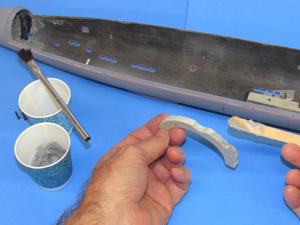
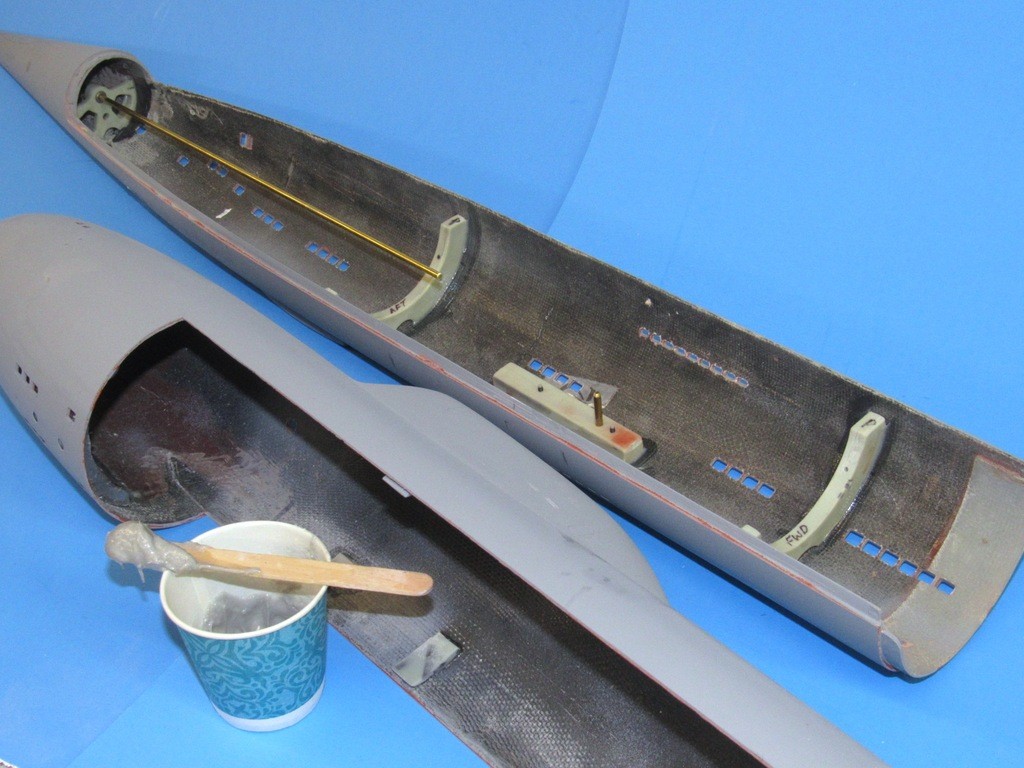
    With the exception of the propeller shaft forward bearing foundation all hardware (resin and Lead) that had to be mounted within the two hull halves were already outfitted with machine screws to hold them in place as I mocked-up things to test for fit and function. It was only after everything was certified as an acceptable system were the resin sub-assemblies taken apart, glued, and re-assembled with the machine screws – this time things were in place for keeps! Glue fillets between parts and hull were formed with forefinger.

    upgrading the SSY 1/96 ALFA kit - Page 2 2frN44

    Straight from the cans, the resin is too thin and ‘runny’ for use as an effective adhesive. Colloidal Silica, depending on the amount, can adjust the mix viscosity from a creamy consistency to one that is clay thick – just depends on the application on how thick you make the adhesive with this stuff.

    The thickened epoxy glue was smeared on each piece before assembly. Here I’m gooping up one of the two SD foundations before screwing it in place within the lower hull.

    upgrading the SSY 1/96 ALFA kit - Page 2 RdhfMo

    Note the long length of 1/8” diameter brass rod projecting from the two propeller bearings. Its purpose here as an alignment gauge – I used it to center the forward propeller shaft bearing foundation as the glue set – I had to be sure that the thrust line fell along the hulls longitudinal axis.

    Note the vertical brass pin projecting from the top of the Indexing pin-Velcro strap foundation piece located between the two SD foundations: The pin fits a hole drilled into the bottom of the SubDrivers ballast tank to hold the SD rigidly in registration with the hull once the securing Velcro strap is made up.

    upgrading the SSY 1/96 ALFA kit - Page 2 WKtRMg


    merriman
    merriman
    Guest


    Posts : 347
    Join date : 2011-10-16
    Age : 75
    Location : Virginia Beach, Virginia

    upgrading the SSY 1/96 ALFA kit - Page 2 Empty Re: upgrading the SSY 1/96 ALFA kit

    Post  merriman Fri Oct 25, 2019 7:39 pm

    Now that the r/c boating season is over – the Groton and Rocky Mount events specifically – I’m back to work in the shop and continue my Scale Shipyard 1/96 ALFA WIP report.

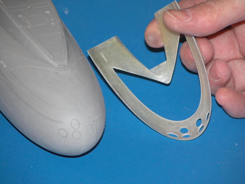
    The last scribing job is a complicated one, requiring a great deal of preparation. Time has come to engrave the six torpedo tube shutter doors at the bow. The below picture shows how I re-scribed the shutter doors on the little Trumpeter 1/144 KILO plastic model kit – this to inform you of how I will tackle the ALFA shutter door engraving job.

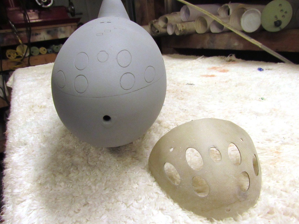
    Basically, I formed a thin-walled GRP scribing stencil blank over the bow of the model. That stencil blank perfectly capturing the sharp compound curve where the shutters are located. Within that GRP blank I drilled, ground, filed and sanded the elliptical openings that would guide my engraving tool as I cut in properly shaped and positioned shutter doors on the models bow.

    (Incidentally, this same stencil also permitted me to engrave the upper sonar window outline to the bow as well).

    upgrading the SSY 1/96 ALFA kit - Page 2 GRaBx7

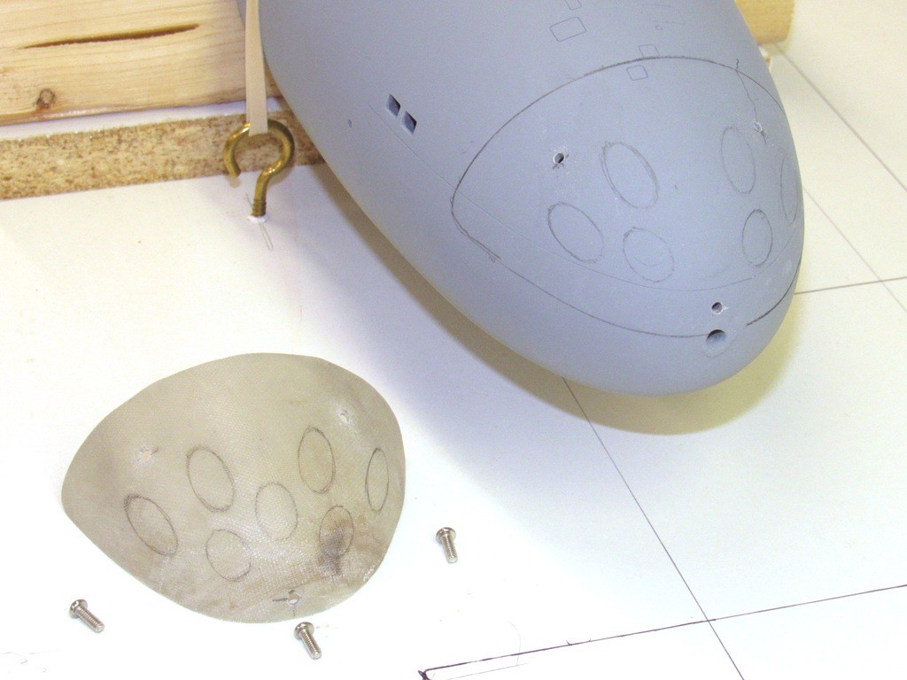
    The end-game is presented here: creation of a GRP scribing stencil blank that has been marked out with the elliptical shapes of the eventual holes that will guide the scribing tool as I engrave the shutter door outlines into the 1/96 ALFA’s bow.

    As was the case for the little KILO model, the same situation exists for the ALFA: Looking straight from the bow what you would see are six perfect circles. However, if viewed at any other aspect, what you would see are ellipses. This because of the sharp compound curves of the bow. Remember, the torpedo tube shutter doors are movable sections of a cylinder. Each of these cylinders penetrates a conical bow at an extreme angle -- in this case six parallel cylinders all in line with the submarines longitudinal axis, and this nest of tubes well above the hulls centerline. Hence the oval shape of each shutter door. The sharper the angle, the more extended the ellipse.

    The remainder of this discussion is how I made the thin walled GRP scribing template blank; and how I devised a mechanical mark-off jig to accurately pencil on the correct shape of each torpedo tube shutter door.

    upgrading the SSY 1/96 ALFA kit - Page 2 TwabPm

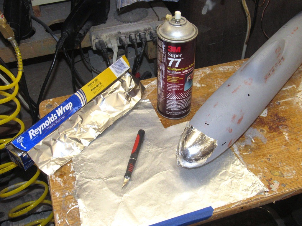
    Making the GRP, thin walled, shutter door scribing blank (stencil) begins by protecting the bow from any direct contact with the strong bonding laminating resin used during the fiberglass cloth lay-up process. To achieve this barrier I prepared some aluminum foil by spray coating one surface with contact-cement. I then burnished a section of this foil to the upper bow. As I wasn’t metal foiling a Century Series fighter plane a few wrinkles in the work were fine, as long as I kept such bumps down to no higher than .005”. The metal barrier took about ten-minutes to rub into place.

    upgrading the SSY 1/96 ALFA kit - Page 2 HJZoQw

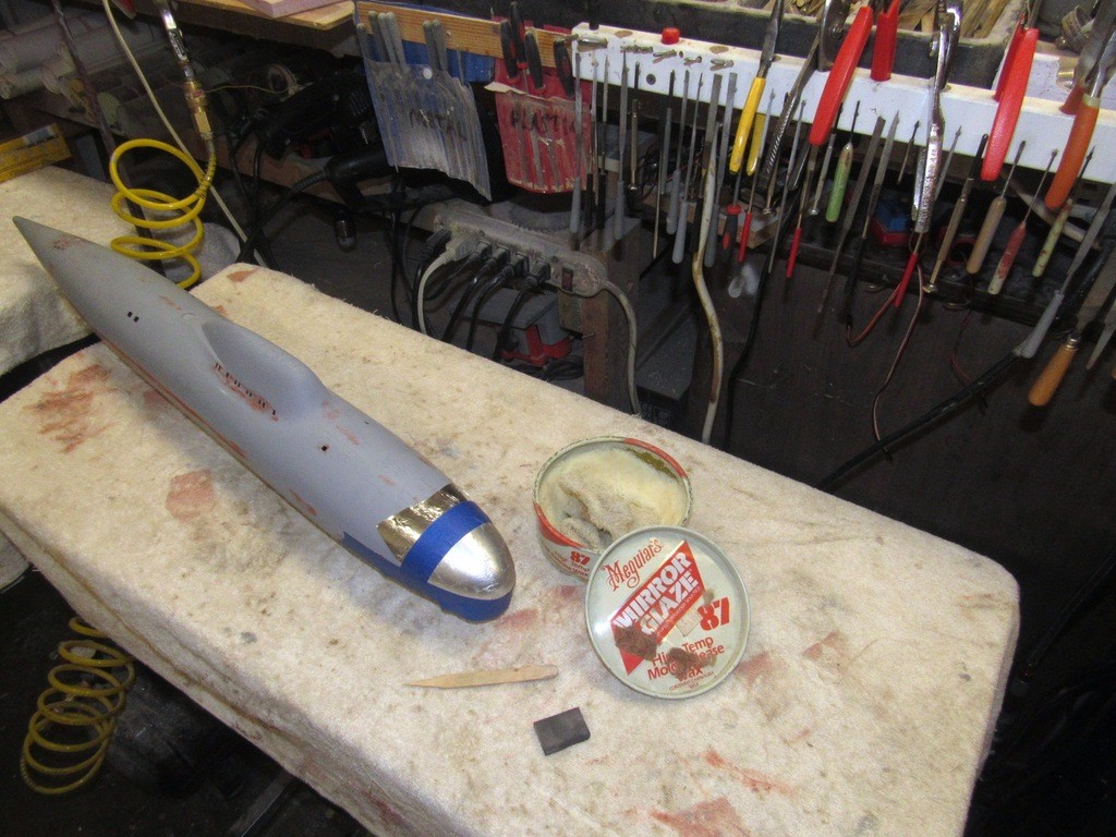
    I applied a radial and equatorial length of masking tape to further protect the surface of the model from any laminating resin that got away from me, and to also produce demarcation edges onto the inside of the GRP stencil blank to identify where I could safely cut away the excess material once the hardened glass laminate was pulled off the bow.

    Several coats of mold-release wax were applied, buffing between layers. Good enough to keep the laminating resin from sticking to the work.

    upgrading the SSY 1/96 ALFA kit - Page 2 YyXrI4

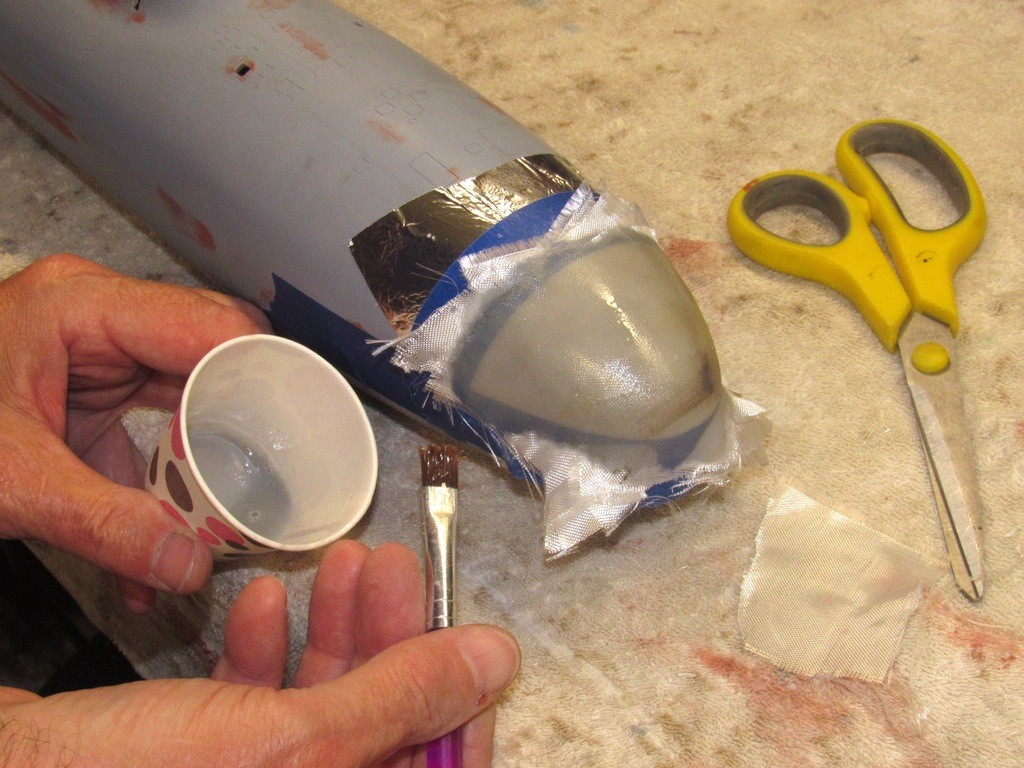
    To negotiate the very tight radius of the compound curve of the bow without wrinkeling I used very light-weight fiberglass cloth. Five laminates for this job. I used old reliable slow-cure West System epoxy laminating resin for the job. Next day the work was well past the green stage and I popped the raw GRP scribing stencil blank off the bow.

    upgrading the SSY 1/96 ALFA kit - Page 2 ZDTNxr

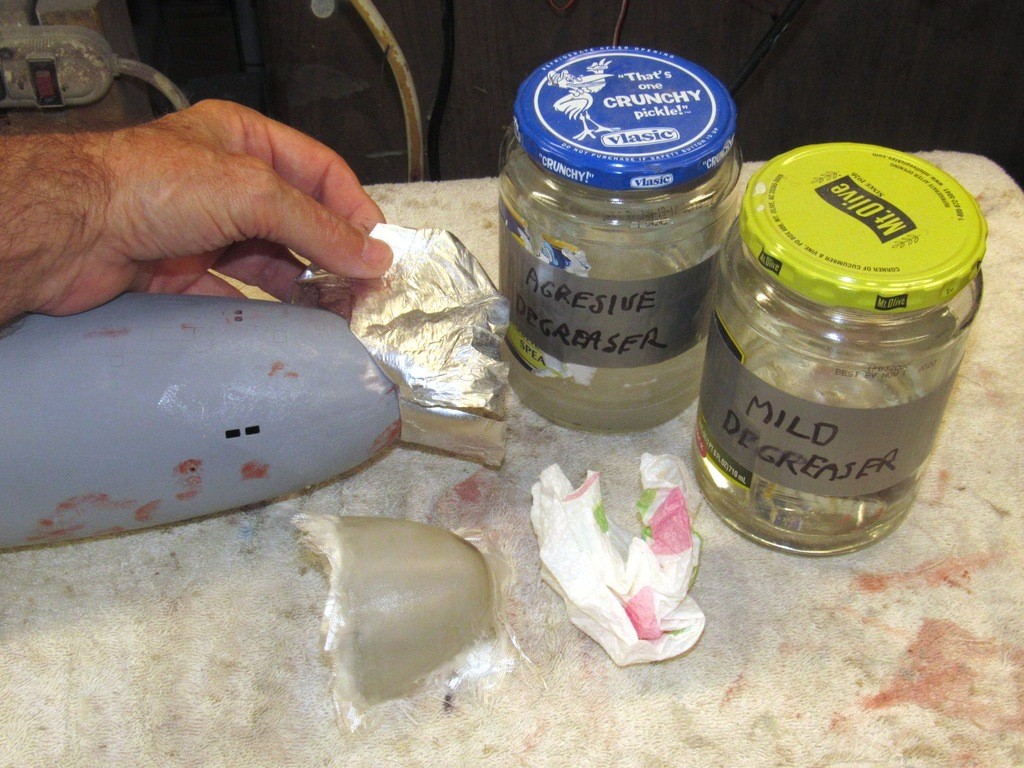
    The only clean-up on the bow after the masking metal foil was removed was to dissolve and remove a small amount of contact-cement that stuck to the model. A mild form of hydrocarbon distillate marketed as a degreasing preparation, intended for car refinishing shops. The solvent is strong enough to cut and remove such adhesives, bird-poop, oils waxes, and dirt. But, the stuff is weak enough not to aggressively cut into the primer, paint, or clear-coat it’s wiped over.

    Though used here to remove adhesive off the models bow, I primarily use the ‘prep’ to clean a models surface before priming, painting, or clear-coating. Note that I have two formulations of prep, one ‘hot’, the other not so hot. The hot stuff is volatile enough to start dissolving the undercoat if rubbed down too hard, so has to be used with care and only on the most filthy of model surfaces.

    upgrading the SSY 1/96 ALFA kit - Page 2 2tx7kF

    So, how does one accurately mark off the bow scribing stencil blank, both assuring correct lateral and height positioning as well as capturing the unique elliptical shape of each shutter door outline?

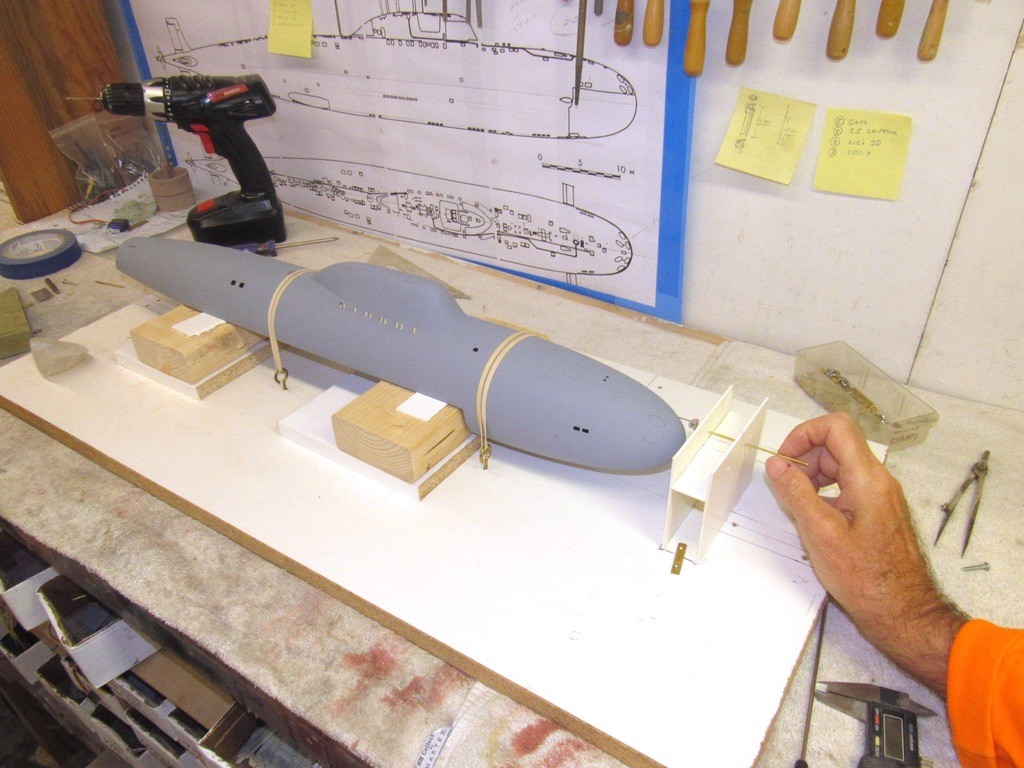
    I make a pencil loaded rotary marking jig, that’s how! A specialized lay-out aid that will describe a circle, but a circle as applied to an oblique surface, like the bow of this ALFA model.

    upgrading the SSY 1/96 ALFA kit - Page 2 89ZQ0W

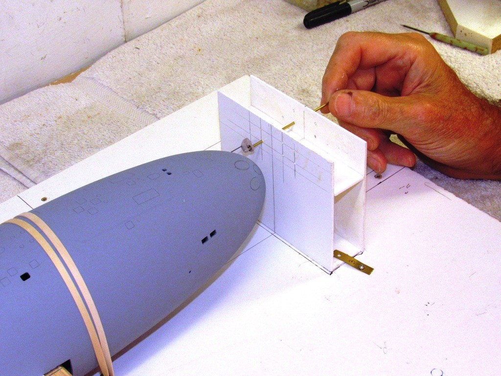
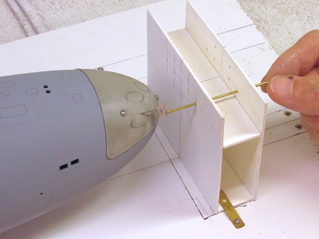
    The box affair, constructed from some scrape .080” Sintra sheet I had kicking around, has appropriately spaced 1/16” holes that pass a piece of brass rod which has at its working end a long, thin, piece of pencil lead. The rod is free to move axially, but is confined in rotation by the box bearing points.

    The ALFA class submarines had tubes sized for 21” diameter weapons. Assuming a few inches of annular space at the shutter doors (shit happens when a torpedo after-body clears the muzzle door and transits the void between torpedo tube and outer hull at high velocity, and entering a chaotic water flow). So, figuring a shutter door diameter of 25”, that gave me a 1/96 scale circle a bit over a quarter-inch. So, duh, that put the pencil lead a bit over an eighth-inch from the center of rotation.

    Before marking the GRP scribing stencil blank I pencil marked the bow itself – good practice, and got me into the process groove before committing to marking the stencil itself. Measure twice, cut once! Practice, practice, practice!

    upgrading the SSY 1/96 ALFA kit - Page 2 6gZQQu

    I trimmed the GRP scribing stencil blank to get rid of the rough edges and corners. To insure a non-slip attachment to the hull I’ve secured the eventual stencil to the bow with 2-56 machine screws. I’ll be applying a lot of lateral force when I start engraving within the holes and I don’t want this thing sliding around buggering up the work. When I’m done with the job it’s no big deal to Bondo the screw holes closed.

    upgrading the SSY 1/96 ALFA kit - Page 2 GvfBTw

    And the moment we’ve all been waiting for: Marking off the shutter door ellipses onto the surface of the scribing stencil blank.

    For my next magical trick, I open up the holes so I can get to the engraving part of the job.
    God damn! Will this thing ever be done!?.........

    upgrading the SSY 1/96 ALFA kit - Page 2 Y3nOH0
    merriman
    merriman
    Guest


    Posts : 347
    Join date : 2011-10-16
    Age : 75
    Location : Virginia Beach, Virginia

    upgrading the SSY 1/96 ALFA kit - Page 2 Empty Re: upgrading the SSY 1/96 ALFA kit

    Post  merriman Sat Nov 16, 2019 7:11 pm


    As it’s been some considerable time since my last posting to this work in progress (WIP) article, so I looked over the last installment for continuities sake. And I find myself using the words, ‘template’ and ‘template’ interchangeably. So, for clarities sake, acknowledging that a template is associated more with graphic work -- though at one stage on this project the engraving template was used as a proper stencil -- I will henceforth describe this engraving guide as a template.

    Words are supposed to have accepted meaning, and it’s my desire not to muddy the lexicon here.

    Time had come to finish the torpedo shutter door scribing template, use it to engrave the model, and move on to other things.

    The equatorially running pen line circling the GRP scribing template denotes where the upper engraved line of the big sonar window is situated on the models bow. I put it on the template to insure that I kept the bottom of the lower four torpedo tubes openings the required 1/16” above that line.

    upgrading the SSY 1/96 ALFA kit - Page 2 JcU8h7

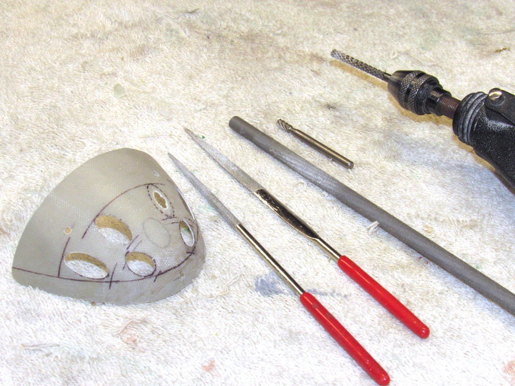
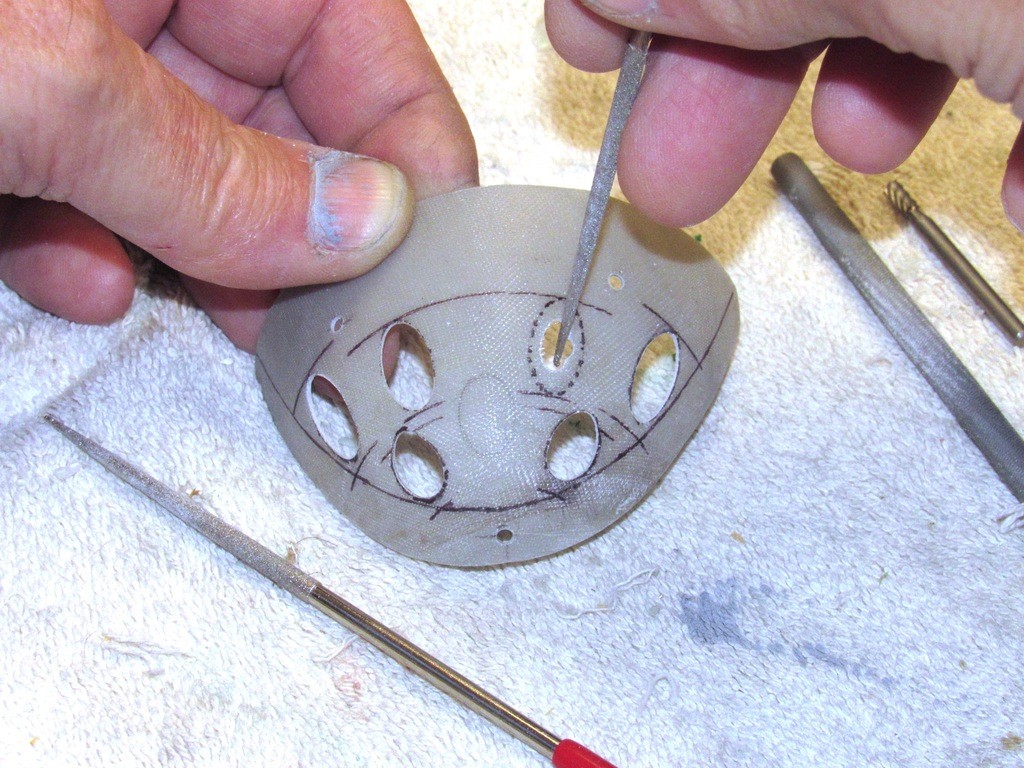
    The template openings were started with a small diameter rotary burr and finished off with a big round-file, diamond Jeweler’s files, and a twist of #240 sandpaper used dry.

    upgrading the SSY 1/96 ALFA kit - Page 2 Az9irf

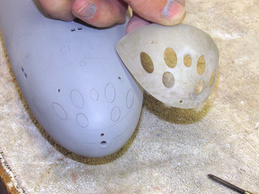
    A final check was to screw the template in place and trace the openings with a pencil. Only in this application can this thing be described as a, stencil. Removing it revealed a subtle inconsistency of the two lower, inboard opening – they did not present as perfect circles when viewing the bow dead-on.

    upgrading the SSY 1/96 ALFA kit - Page 2 NSp0gC

    Correction was ground into the template, and the pencil test performed again using the … err … stencil. Perfect! The template was ready for use.

    upgrading the SSY 1/96 ALFA kit - Page 2 6zJmSh

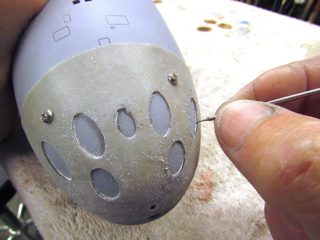
    Once I was happy with the pencil test, I remounted the template and scribed out the torpedo tube shutter doors as well as the smaller diameter torpedo handling skid support access port.

    upgrading the SSY 1/96 ALFA kit - Page 2 Gm4sOD

    The skid support access port is an interesting item seen on many Russian designs; a feature that permits  boats to load and off-load their weapons through the above waterline torpedo tubes rather than a dedicated torpedo loading hatch/door set above the torpedo room.

    The ALFA is an extreamly deep diving submarine and its internal volume is very tightly packed; the need to minimize closures exposed to sea-pressure is apparent, as is the elemination of traditional torpedo handeling  gear.

    upgrading the SSY 1/96 ALFA kit - Page 2 PzSUC0

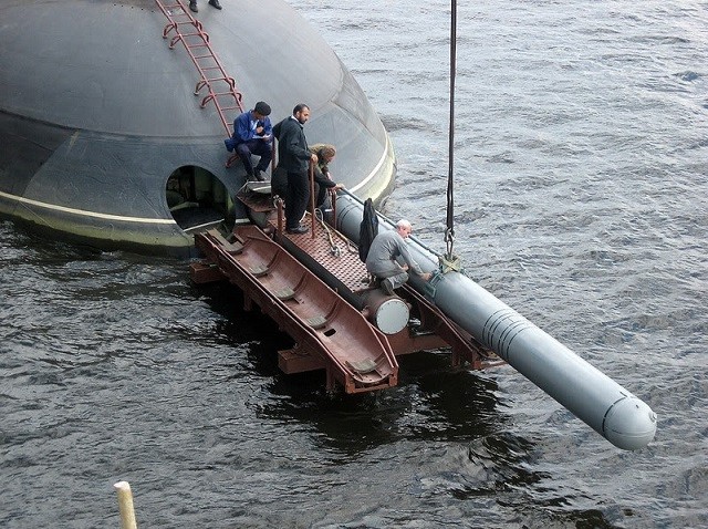
    Though not an ALFA pictured below is torpedo loading gear used on a KILO class submarine. Very similar to that employed by the ALFA’s. The wight of the loading/off-loading torpedo skids, the weapons themselves, and crew involved in the operation is all born by a large diameter, very stout cylindrical keel that sleeves into a foundataion set in the space between the bow and torpedo room forward bulkhead.

    See that dude at the base of the access ladder with a check-list in his lap? His feet are planted atop the opened skid support access port.

    Iranian’s me thinks. Sand-crabs (civilian yard workers) likely. Russia will sell boats to anybody!
     
    Hey, so would we, if only our government permited our yards to sell submarines to ‘friendly’ client nations. Like Turkey; Greece; Vietnam; Pakastan; Croatia; North Korea; Syria; Nigeria; Lybia; Saudi Arabia; Mexico; Poland; and the drug cartells (those are nation-states, right?).

    Money would be good and it would keep our submarine design and building infrastructure up to speed.

    I now duck for cover.

    upgrading the SSY 1/96 ALFA kit - Page 2 SQwzEn

    When engraving into any substrate – in this case very receptive gel-coat, some spots of air-dry putty, and primer – no matter how well the material(s) respond to the cutting action of the engraving tool tip, there invariably will be minute chips at the surface of the model. This compels the careful model-builder/kit-assembler to over-coat the work with a very thin layer of touch-up putty, chasing it out of the engravings and later wet sanding the surface and giving the work a final light-touch scribing to remove all sanding dust from the engraved lines.

    upgrading the SSY 1/96 ALFA kit - Page 2 BdlC2G

    Ta-Dah! Some touch up work on the little louver slits at the after end of the sail – more on that work later; fair in the stabilizer fillets with the hull; and I’ll be ready for paint!

    I’ve already closed up the three template securing screw holes with some Bondo, touch-up putty, and primer, sanding between each step with a piece of block backed #400 sandpaper. Closing up this remaining 1/8” hole at centerline will soon follow -- it was retained long enough to take advantage of the marking-boards ability to assure proper alignment of the four stern stabilizers as I permanently affixed them to the hulls stern.

    upgrading the SSY 1/96 ALFA kit - Page 2 Rw5XuE

    upgrading the SSY 1/96 ALFA kit - Page 2 M6P0lE
    merriman
    merriman
    Guest


    Posts : 347
    Join date : 2011-10-16
    Age : 75
    Location : Virginia Beach, Virginia

    upgrading the SSY 1/96 ALFA kit - Page 2 Empty Re: upgrading the SSY 1/96 ALFA kit

    Post  merriman Wed Nov 20, 2019 3:05 am

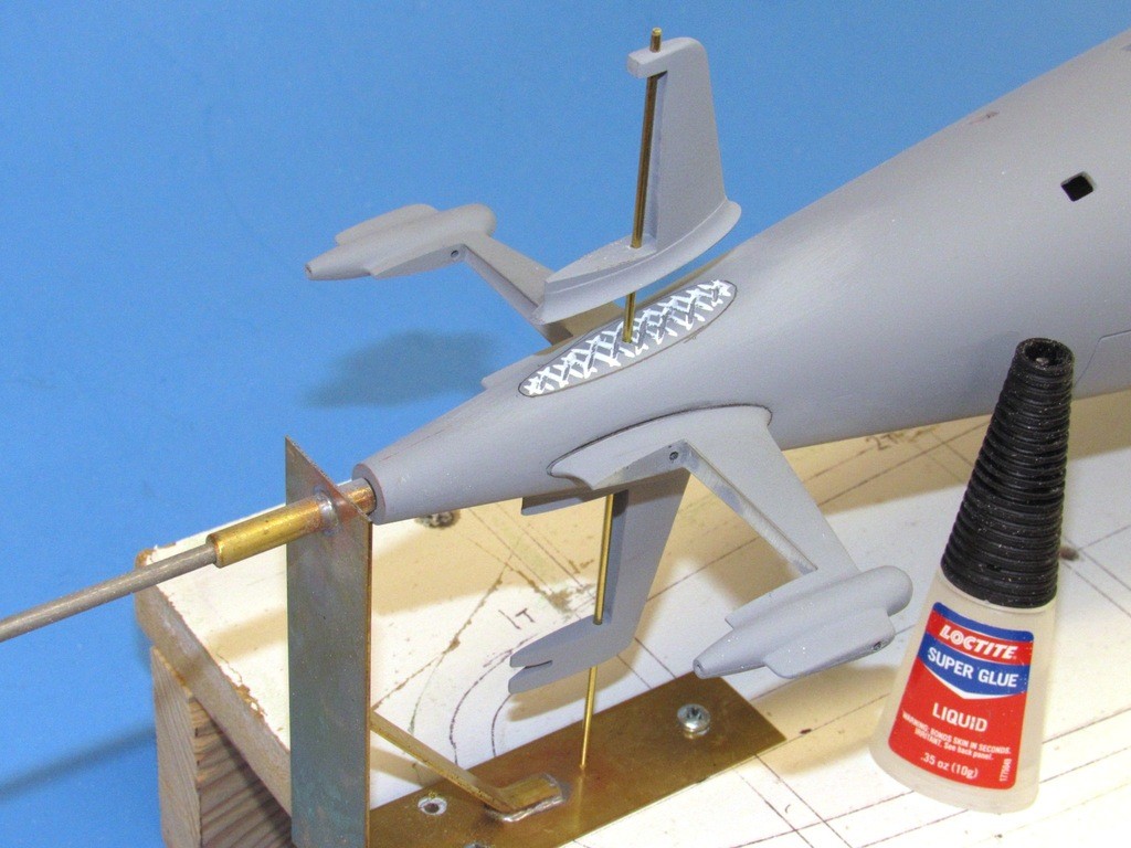
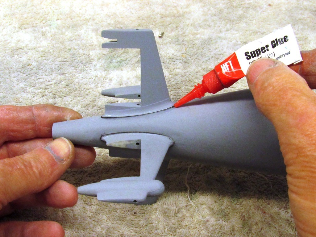
    Using a pass-through length of 1/16” brass rod as an alignment aid I suspended a stabilizer over the work, then applied CA adhesive to the deeply roughed-up surface of the hull. The cross-hatching insures plenty of ‘tooth’ and increased bonding surface area.

    But before all that I took very careful measures to insure that each stabilizer was oriented about the roll, pitch and yaw axis (in relation to the hulls longitudinal axis) correctly: the pass-through rod assuring roll, my eye-ball working out the yaw and pitch. Alignment established on a stabilizer I marked its outline onto the hull with a pencil – a guide to follow when it came time to grind in the cross-hatching, and gluing things together.

    Proper planning prevents piss-poor performance (shop-class, 101).

    upgrading the SSY 1/96 ALFA kit - Page 2 O3Pg8A

    Once an opposed set of stabilizers were glued down, their pass-through rod was removed, and the other set of stabilizers attached to the hull in a like manner.

    Though I took great care to get the base of the stabilizers to conform to the compound curve of the hull there still remained a slight gap where stabilizer fillet met hull, I had to address that; not only a gap to fill, but also a slight ‘step’ between hull and where the stabilizer fillet met the hull. Those steps had to be filed down to a feather-edge to the hull. Sure, a time consuming and rather intense operation, but worth the effort.

    upgrading the SSY 1/96 ALFA kit - Page 2 B7ZU6O

    I held back on the CA when I initially bonded the stabilizers to the hull, only providing a minimal drop at the extreme ends where the stabilizer would sit – the objective was to not get any of the glue on the temporarily installed pass-through guide rod; doing so would have presented a nightmare trying to yank the damned thing out!

    So, after all the stabilizers were in place and the pass-through rods yanked out I finished the gluing job by applying plenty of thin formula CA to the step/edge, where fillet met hull, and let capillary action draw the glue into all voids between stabilizer and hull. Once cured (‘accelerator’ is our friend!) the additional glue not only enhanced the strength of the bond, but also acted as a filler or ‘grout’ that helped fair stabilizer to hull when I later went at it with round-files.

    upgrading the SSY 1/96 ALFA kit - Page 2 SdJse0

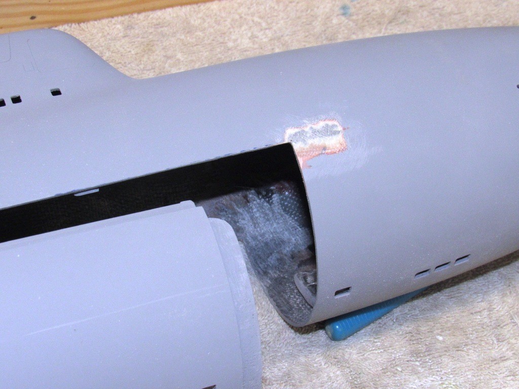
    So, I get back to work on this ALFA project after a week of doing other ‘stuff’, and what does it greet me with?! The SOB has developed an advancing crack on the starboard side, originating at the right-angle corner between where I bonded the forward end of the lower hull to the upper hull; the crack running along the joint line between the halves, heading towards the bow. Yikes!

    I examined the interior only to find that (for some stupid reason) I had neglected to internally reinforce the bond between the two hull sections with plenty of overlapping GRP tape. Only bonding resin (and not much of it) used way back at the beginning of this project was the only thing bonding the pieces together. No fiberglass tape. Just resin. Idiot!

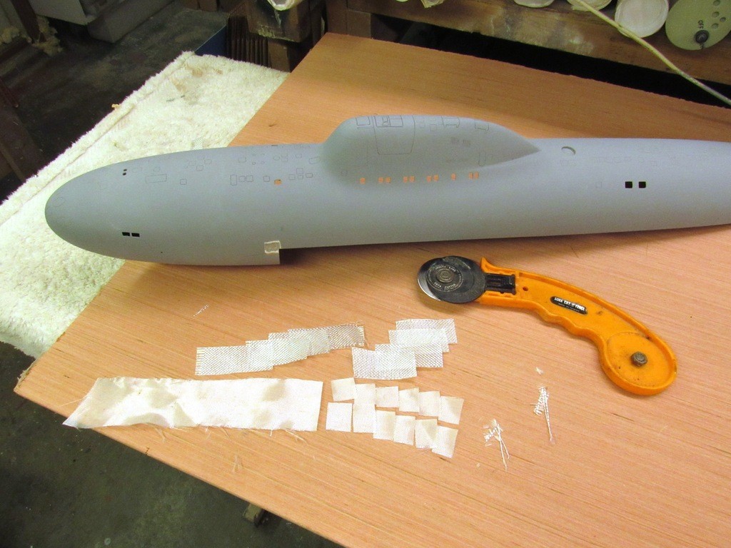
    The only thing to do was to grind away material from the outside where the crack was – and a good ½” further forward, for insurance, and to laminate reinforcing squares of fiberglass cloth, about five layers. The light stuff first followed by some four-ounce cloth on top. Did the same for the inside seam, both sides; those internal reinforcing strips running a bit farther toward the bow.

    upgrading the SSY 1/96 ALFA kit - Page 2 BPzrQH

    This is the outboard GRP repair already filed and sanded to contour and ready for touch-up putty. You can still make out the weave of the fiberglass cloth through the transparent laminating resin. The inboard reinforcement can be seen as well.

    Now there is no possibility of crack migration from the sharp corner between upper and lower hull! Better to make the fix now than later. Disaster averted. I would have lost my mind if that crack showed up after I had painted and weathered the model.

    upgrading the SSY 1/96 ALFA kit - Page 2 JthHSP

    Smooth to the touch it may be, but invariably there will be little voids and tool-marks atop the glass fix. After such work I don’t even bother with primer – I go straight to either a two-part filler or, as in this case, an air-dry touch-up putty. Here, applied neat from the tube to the work with a semi-stiff brush.

    upgrading the SSY 1/96 ALFA kit - Page 2 DgX92z

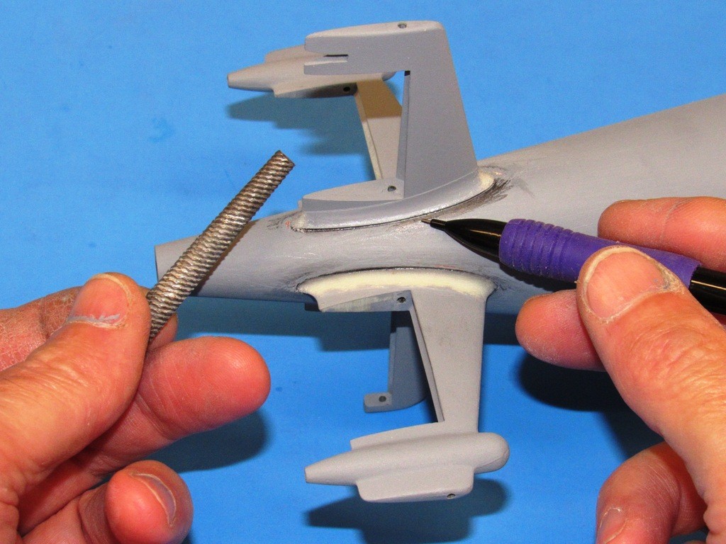
    Try as I might to achieve a tight, gap free union between stabilizer fillet and hull I still wound up with a slight gap between the two structures. That slight step had to be knocked down to a feather-edge transition. The best tool for that job is this nasty looking, first-cut, rat-tail file. Course enough to shave off significant hunks of resin, meaning fewer strokes of the tool to eliminate the fillet-hull steps. This of course requires very careful strokes of the tool.

    As a canary-in-the-coal mine aid, informing me when I’m getting too close to the adjacent hull was the pencil marking of the hull, from fillet step down about a 1/8” onto the hull.

    upgrading the SSY 1/96 ALFA kit - Page 2 PWYG0j

    The rough work with the rat-tail file done I went over the work with brush applied air-dry touch-up putty applied neat from the tube; The putty filling tool-marks and what step gaps remained.

    upgrading the SSY 1/96 ALFA kit - Page 2 QcMeeU

    The ideal round-file diameter is, of course, one that is twice the fillet radius. And I found just the right one in my rather massive collection of files – this particular one part of a set of chain-saw sharpening files bought at the local hard-ware store. Using it dry – If used wet it’s harder to see the progress of cutting – I carefully shaved away the excess putty until I had a seamless union between stabilizer fillet and hull. A careful wet sanding with a twist of #400 grit sandpaper and things were ready for a shot of primer.

    upgrading the SSY 1/96 ALFA kit - Page 2 Prt2ps

      Current date/time is Mon Dec 02, 2024 7:44 pm