The Association of Model Submariners.

Would you like to react to this message? Create an account in a few clicks or log in to continue.

* THE FORUM FOR ALL THOSE INTERESTED IN BUILDING AND OPERATING MODEL SUBMARINES *


Join the AMS - Registered Forum users can become members of the AMS and it's free ...... To join send an email with your name , address and phone number to amstreasure@googlemail.com


For a guide to past events see the "Shows and Events" section.

Papplewick Pumping Station SUBMARINE Day. 31st March - 1st April 2024.

$$$

&&&

::::

Who is online?

In total there are 4 users online :: 0 Registered, 0 Hidden and 4 Guests :: 1 Bot

None


Most users ever online was 180 on Tue Nov 05, 2019 6:03 am

Latest topics

» Information on camouflage patterns for German seahund
UHF radio control  for submarines (openLRS, LoRa, FSK  etc. on 458Mhz and 433Mhz ) - Page 7 EmptyFri Mar 15, 2024 4:36 pm by david f

» WW2 mini sub build
UHF radio control  for submarines (openLRS, LoRa, FSK  etc. on 458Mhz and 433Mhz ) - Page 7 EmptyTue Mar 12, 2024 1:56 pm by geofrancis

» Not the hobby I expected :)
UHF radio control  for submarines (openLRS, LoRa, FSK  etc. on 458Mhz and 433Mhz ) - Page 7 EmptySun Mar 10, 2024 6:30 pm by cat

» 868/915 Mhz as a viable frequency for submarines.
UHF radio control  for submarines (openLRS, LoRa, FSK  etc. on 458Mhz and 433Mhz ) - Page 7 EmptyWed Mar 06, 2024 4:50 pm by tsenecal

» Sheerline gasket material
UHF radio control  for submarines (openLRS, LoRa, FSK  etc. on 458Mhz and 433Mhz ) - Page 7 EmptyMon Feb 19, 2024 9:24 pm by Michaelc

» Choice of CAD software and Printer for 3D printing
UHF radio control  for submarines (openLRS, LoRa, FSK  etc. on 458Mhz and 433Mhz ) - Page 7 EmptyThu Feb 15, 2024 1:53 pm by david f

» Engel Nautlus
UHF radio control  for submarines (openLRS, LoRa, FSK  etc. on 458Mhz and 433Mhz ) - Page 7 EmptyTue Feb 13, 2024 9:15 am by palmert6

» RF 27/433MHz maximum depth in pools (1-5 ppm chlorine, 6-8pH)
UHF radio control  for submarines (openLRS, LoRa, FSK  etc. on 458Mhz and 433Mhz ) - Page 7 EmptyThu Feb 08, 2024 2:05 pm by david f

» Arduino proportional control of a piston tank
UHF radio control  for submarines (openLRS, LoRa, FSK  etc. on 458Mhz and 433Mhz ) - Page 7 EmptyThu Feb 08, 2024 1:37 pm by david f

Statistics

Our users have posted a total of 12425 messages in 1980 subjects

We have 1003 registered users

The newest registered user is Stefan Udovenko КПДЮ

+17
Uptona
Nickj_UK
C-3PO
thegrimreaper
Deep Diver (Fred)
Crossie
John Wrennall
tsenecal
bwi
merriman
DAVE J
salmon
nigele(ADMIN)2
Hermann
johnrobinson
Tom(ADMIN)
david f
21 posters

    UHF radio control for submarines (openLRS, LoRa, FSK etc. on 458Mhz and 433Mhz )

    thegrimreaper
    thegrimreaper
    Guest


    Posts : 119
    Join date : 2010-12-01
    Age : 64
    Location : Ellesmere Port

    UHF radio control  for submarines (openLRS, LoRa, FSK  etc. on 458Mhz and 433Mhz ) - Page 7 Empty Re: UHF radio control for submarines (openLRS, LoRa, FSK etc. on 458Mhz and 433Mhz )

    Post  thegrimreaper Tue Nov 21, 2017 9:08 am

    Hi Tim,

    https://www.ofcom.org.uk/

    OfCom is the official office for our communications here in the U.K. they govern the airways and have far reaching powers through our courts over anything to do with cable or wireless transmitions within the borders of the U.K.

    Regards Mark.
    avatar
    tsenecal
    Guest


    Posts : 305
    Join date : 2015-04-01

    UHF radio control  for submarines (openLRS, LoRa, FSK  etc. on 458Mhz and 433Mhz ) - Page 7 Empty Re: UHF radio control for submarines (openLRS, LoRa, FSK etc. on 458Mhz and 433Mhz )

    Post  tsenecal Tue Nov 21, 2017 9:03 pm

    Mark,

    i figured you guys would know who Ofcom is, and it appears i hit the right site by sheer accident.  they appear to be the equivalent to our FCC here in the states.   i would definitely see if they have a specific definition of "remote controller", and verify if the devices we/you use will fall under that definition. if the definition works, that would make 868mhz a viable alternative. I ran my 915mhz equipment at a recent model sub regatta, with as good a performance from the 3 915mhz subs as i did from the single 433mhz sub.
    avatar
    tsenecal
    Guest


    Posts : 305
    Join date : 2015-04-01

    UHF radio control  for submarines (openLRS, LoRa, FSK  etc. on 458Mhz and 433Mhz ) - Page 7 Empty Re: UHF radio control for submarines (openLRS, LoRa, FSK etc. on 458Mhz and 433Mhz )

    Post  tsenecal Fri Nov 24, 2017 4:31 pm

    just so that you understand why i have gone to the effort for the research on the 868mhz equipment... there are several commercial products that are either available or will be available soon that are 868mhz, designed specifically "for the european market"... i also understand that "european market" doesn't necessarily mean "UK"... but it does bear researching to verify

    http://fpvlab.com/forums/showthread.php?51594-FrSky-R9-R9M-module-900Mhz-(868Mhz-EU)-Long-range-system
    david f
    david f
    AMS Treasurer


    Posts : 2395
    Join date : 2010-11-10
    Age : 73
    Location : Cumbria

    UHF radio control  for submarines (openLRS, LoRa, FSK  etc. on 458Mhz and 433Mhz ) - Page 7 Empty Re: UHF radio control for submarines (openLRS, LoRa, FSK etc. on 458Mhz and 433Mhz )

    Post  david f Fri May 17, 2019 12:14 pm

    I have just ordered and received another couple of Orange 433Mhz receivers from Hobbyking.
    So they are still available and took 17 days to arrive.

    David
    avatar
    Nickj_UK


    Posts : 11
    Join date : 2019-01-24
    Location : Cheltenham

    UHF radio control  for submarines (openLRS, LoRa, FSK  etc. on 458Mhz and 433Mhz ) - Page 7 Empty Re: UHF radio control for submarines (openLRS, LoRa, FSK etc. on 458Mhz and 433Mhz )

    Post  Nickj_UK Mon May 27, 2019 9:55 pm

    Just out of interest I acquired a pair of Arduino nano's which have onboard 868mhz transceivers. I only picked these up as they are a known quantity and there is plenty of info and field tests on these specific units.
    I've also disemboweled an old 4 channel 2.4 transmitter purely because the trims are mechanical and simply advance/retard devices.
    At the moment the boards 'chirp' quite happily to each other over a reasonable line of sight (as far as I was happy to walk as extreme range isn't an issue) and the nominated transmitter continued to send a test signal and received confirmation of the signal with virtually no loss of signal strength.
    Next thing is to read and encode the tx components and add that to the tx signal with a decode at the receiver and conversion to a signal for servo's/switches and I'll have a working tx/rx combo.

    It's really the frequency that is at issue,as senecal noted OFCOM says 'These applications include home/office automation, access control, remote controllers, medical, telecare, smart meters, telemetry'.
    I think that by remote controllers they mean the small click on off devices, everything else in the inclusions is going to be more occasional signal pulses rather than what we would want, an almost continuous signal which is more the role envisaged for 915.
    So 868 is an experiment as 915 boards don't cost any more (I just couldn't find the ones I wanted at the time) and the code is all transferable between base arduino's.
    It's also possible to add a few more odds and ends like multiaxis gyros (levelling), pressure sensors (depth control) and custom OLED displays albeit very small.


    Last edited by Nickj_UK on Mon May 27, 2019 9:58 pm; edited 1 time in total (Reason for editing : added a bit)
    avatar
    tsenecal
    Guest


    Posts : 305
    Join date : 2015-04-01

    UHF radio control  for submarines (openLRS, LoRa, FSK  etc. on 458Mhz and 433Mhz ) - Page 7 Empty Re: UHF radio control for submarines (openLRS, LoRa, FSK etc. on 458Mhz and 433Mhz )

    Post  tsenecal Tue May 28, 2019 9:19 pm

    Nickj_UK,

    what brand/model radio did you pick up? most traditional fm style radios will output a ppm signal to the RF deck, but a lot of the newer 2.4ghz systems are "digital" for the entire workflow, and much harder to find a signal that can be "hijacked"...
    avatar
    Nickj_UK


    Posts : 11
    Join date : 2019-01-24
    Location : Cheltenham

    UHF radio control  for submarines (openLRS, LoRa, FSK  etc. on 458Mhz and 433Mhz ) - Page 7 Empty Re: UHF radio control for submarines (openLRS, LoRa, FSK etc. on 458Mhz and 433Mhz )

    Post  Nickj_UK Tue May 28, 2019 11:15 pm

    It's a generic 4 channel, E sky 2.4 ghz tx. There are the usual two twin axis sticks and there was a trainer switch.
    The encoder board and tx board where seperate discrete pcb's, as I am going to use the arduino to capture the stick positions and the digital inputs of on/off switches then the encoder board becomes redundant.
    The tx board is replaced by the tranceiver piggy backed on the arduino so again the original becomes redundant.
    I just (mostly simply) measure the volts out of the pots using the arduinos built in ADC's, put a that into a string of data that becomes the tx signal.
    The receiver arduino converts the numbers in the signal to an output to drive the servos, it'll also send back a signal reception strength (these LoRa's are all tranceivers so do 2 way) that the rx end can display it. That can also act as a 'panic' trigger to put planes to rise and blow tanks.

    I've added a further two rotary pots for two more analogue inputs and a pair of switches for simple digital on/off switches.
    I might swap a one of the rotary (or both) for a 3 way switch to give a hi/mid/low output from the tx which would be more useful for driving a piston tank controller.

    As this has cost me the grand sum of £40ish so far for arduino boards, pots switches tranceivers and the original transmitter I won't be too worried if it doesn't work as planned. I can reuse most everything in other projects.
    Mostly it's just being doing for the fun of it and the possibility that I'l get something at the end that works and works in the way I want it to.

    Otherwise I'll just use one of my 2.4 computer tx's with a hacked 40mhz module, my F14 (14 available channels but a limited number of crystals ) or the brand new old stock synthesised multiplex 40mhz tx I recently acquired (nice if an odd menu system).
    C-3PO
    C-3PO


    Posts : 95
    Join date : 2018-11-21
    Location : Northamptonshire UK

    UHF radio control  for submarines (openLRS, LoRa, FSK  etc. on 458Mhz and 433Mhz ) - Page 7 Empty Re: UHF radio control for submarines (openLRS, LoRa, FSK etc. on 458Mhz and 433Mhz )

    Post  C-3PO Mon Jun 03, 2019 11:09 pm

    Hi Nickj_UK,

    Interesting posts - what transceiver is it on the Arduino Nano boards that you recently aquired?

    Regards

    Jonathan
    avatar
    Nickj_UK


    Posts : 11
    Join date : 2019-01-24
    Location : Cheltenham

    UHF radio control  for submarines (openLRS, LoRa, FSK  etc. on 458Mhz and 433Mhz ) - Page 7 Empty Re: UHF radio control for submarines (openLRS, LoRa, FSK etc. on 458Mhz and 433Mhz )

    Post  Nickj_UK Tue Jun 04, 2019 8:36 am

    The boards I have to experiment with are these Transceivers.
    Not the highest range units but for a sub it is really a bit arbitary, after all is it likely that you'll be running on the surface at something like 6km range!!


    C-3PO
    C-3PO


    Posts : 95
    Join date : 2018-11-21
    Location : Northamptonshire UK

    UHF radio control  for submarines (openLRS, LoRa, FSK  etc. on 458Mhz and 433Mhz ) - Page 7 Empty Re: UHF radio control for submarines (openLRS, LoRa, FSK etc. on 458Mhz and 433Mhz )

    Post  C-3PO Tue Jun 04, 2019 8:58 am

    Hi - Thanks for info - that looks like a HOPE RF device plonked on the board - probably - RFM92W-868S2

    It also looks like you can select the operating frequency by changing device registers.

    Do you know if there is a duty cycle restriction with the board you have tested?

    Regards
    Jonathan
    avatar
    Nickj_UK


    Posts : 11
    Join date : 2019-01-24
    Location : Cheltenham

    UHF radio control  for submarines (openLRS, LoRa, FSK  etc. on 458Mhz and 433Mhz ) - Page 7 Empty Re: UHF radio control for submarines (openLRS, LoRa, FSK etc. on 458Mhz and 433Mhz )

    Post  Nickj_UK Tue Jun 04, 2019 2:57 pm

    All of these drop power output (so decrease range) you increase the frequency of transmissions, this is to prevent overheating I believe. Quite by how much is a very good question and I'll probably end up needing a higher output transceiver to account for this. These were after all designed for the Internet Of Things which would typically use a very brief and occasional signal, after all who needs to check (as an example) soil for moisture a few times a second to control an automatic irrigation system? I'm going to start with 4 chirps a second and ramp up from there. I've not got anything that will be physically very fast, depth keeping and levelling are to be managed by an AD2 & DC from Kevin McLeod so a 'slow' response is probably less of an issue than it might seem.
    To avoid too much of this throttling the sent message needs to be brief so there can be a sleep period between chirps. All I'm planning on sending are the control stick & switch positions with the receiver converting them to the servo output. I could as easily send the stick positions as servo positions though I'm not sure that would make any difference to the to signal content as they will be very similar length numbers.
    In any case one or other end of the Rx Tx combo will allow modifications to the values, I'm thinking along the lines of keeping the Tx end just stick positions and then tune the Rx output to the boat.

    Oh Yes the frequency seems to be selectable but the ariels need to be different lengths for each.
    C-3PO
    C-3PO


    Posts : 95
    Join date : 2018-11-21
    Location : Northamptonshire UK

    UHF radio control  for submarines (openLRS, LoRa, FSK  etc. on 458Mhz and 433Mhz ) - Page 7 Empty Re: UHF radio control for submarines (openLRS, LoRa, FSK etc. on 458Mhz and 433Mhz )

    Post  C-3PO Tue Jun 04, 2019 3:03 pm

    It's a fascinating topic - I will look out for your updates on progress

    I am on a similar path but on 459mhz

    Regards
    Jonathan
    david f
    david f
    AMS Treasurer


    Posts : 2395
    Join date : 2010-11-10
    Age : 73
    Location : Cumbria

    UHF radio control  for submarines (openLRS, LoRa, FSK  etc. on 458Mhz and 433Mhz ) - Page 7 Empty Re: UHF radio control for submarines (openLRS, LoRa, FSK etc. on 458Mhz and 433Mhz )

    Post  david f Sat May 02, 2020 8:42 am

    Just a note to say that I have uploaded two sample files for openLRS transmitter and receiver configuration on the "Files" section of our Facebook site. (My thanks to Tim G for showing the way on this. You will need to rename the .zipp files to .zip files to unzip them.)

    These will get you started and get you onto the recommended UK legal frequency of 458-459 Mhz.

    David
    avatar
    Uptona


    Posts : 1
    Join date : 2020-07-11

    UHF radio control  for submarines (openLRS, LoRa, FSK  etc. on 458Mhz and 433Mhz ) - Page 7 Empty Re: UHF radio control for submarines (openLRS, LoRa, FSK etc. on 458Mhz and 433Mhz )

    Post  Uptona Sat Jul 11, 2020 12:27 pm

    David, Tim,
    I’ve read with interest this post as somebody who is new to this hobby.
    I am finishing my first model submarine and need to acquire a suitable transmitter radio and receiver set for use in UK. I’ve quickly learnt 40Mhz devices are scarce and arguably prefer something future proof.
    Are the Orange OpenLrs modules I’ve read about the way to go and what new radio transmitter would you start with and will the said modules drop in ?

    If you could point me to where such devices are available for me to consider that would be really helpful.
    david f
    david f
    AMS Treasurer


    Posts : 2395
    Join date : 2010-11-10
    Age : 73
    Location : Cumbria

    UHF radio control  for submarines (openLRS, LoRa, FSK  etc. on 458Mhz and 433Mhz ) - Page 7 Empty Re: UHF radio control for submarines (openLRS, LoRa, FSK etc. on 458Mhz and 433Mhz )

    Post  david f Tue Jul 14, 2020 8:14 am

    I wish there was an easy "off the shelf" availability of openLRS equipment suitable for "beginners" but it is not that simple. Lack of commercial suppliers of equipment continues to be one of the major problems in our hobby.

    The frequency for r/c equipment is heading ever upwards and this creates problems for model submariners who need lower frequency signals that propagate in water.  2.4 Ghz is useless for us. We once had a good supply of drone equipment at 433 Mhz (which we could configure to the UK legal frequency of 458Mhz). But drone enthusiasts have moved up to about 800Mhz which is less good for us. Tim Senecal (who pioneered openLRS for subs) has shown that equipment at this frequency can be used for subs. (The UK is typically independent in that we are the only country using 458 MHz! In the US they can use 433 but have to pass on online exam first.)

    Some links from Tim regarding 800Mhz equipment:

    https://www.banggood.com/FrSky-Taranis-Q-X7-ACCESS-2_4GHz-24CH-Mode2-Transmitter-with-R9M-2019-Long-Range-Module-for-RC-Drone-p-1612732.html?rmmds=search&ID=2336279156&cur_warehouse=CN

    https://www.banggood.com/FrSky-R9-900MHz-16CH-Long-Range-RC-Receiver-R9M-Module-System-p-1152994.html?akmClientCountry=GB&p=6L1818635832201406F2&cur_warehouse=CZ

    The only supplier of 433 Mhz openLRS RXs and TX modules, that I know of, is Hobbyking and they are out of stock of RXs at the moment. Flytron in the UK no longer supply this equipment.

    https://hobbyking.com/en_us/orangerx-open-lrs-433mhz-transmitter-1w-jr-turnigy-compatible.html?queryID=5153abbff8c2c9fc2790af5d2da25b13&objectID=46651&indexName=hbk_live_magento_en_us_products

    It also used to be possible to drop an openLRS module into the back of Futaba and JR Txs but I don't think these are available other than secondhand.

    My, UK specific, advice to you would be to buy the Hobbyking TX and RX modules when they both come back into stock. (They are not expensive). Uploading the open source openLRS software would be easy for you if you have experience of (say) Arduinos. (To avoid frying the modules always  have an aerial connected and also check the continuity of the aerial coax. I have had reports and experienced one module where the earth screen was not connected. The TX module can transmit at 1 Watt but 100 mW is the maximum power in the UK. You can set the power output in the Chrome configurator setup.)

    You will need to connect the TX module to a transmitter via the trainer socket. It will be a little bit of a "Frankentransmitter" as a US colleague named it but you can easily add useful things like telemetry (see my thread on here.) so it would be worth the effort at not much cost.

    You could also try the 800Mhz option that Tim has tried. (See link above and I hope Tim updates us on this and the Russian supplier option. Fortunately nothing seems to be available from Huawei - joke!)

    Sorry that it involves a fair bit of research and DIY. It would help everyone in the hobby if you could report back on here on the availability of equipment.

    It seems to me that there is a commercial opportunity for somebody to provide specialised (and premium priced!) submarine radio control equipment running at 400 or 800 Mhz (or come to think about it - 40Mhz!).
    david f
    david f
    AMS Treasurer


    Posts : 2395
    Join date : 2010-11-10
    Age : 73
    Location : Cumbria

    UHF radio control  for submarines (openLRS, LoRa, FSK  etc. on 458Mhz and 433Mhz ) - Page 7 Empty Re: UHF radio control for submarines (openLRS, LoRa, FSK etc. on 458Mhz and 433Mhz )

    Post  david f Mon Jul 20, 2020 11:49 am

    I have had email conversation with Tim Senecal who pioneered the openLRS system for subs. I attach it in full below:

    Hi Tim,

    I am trying to give an answer to a UK guy on this over on the AMS forum but I don't know much about the above Russian supplier.

    Where can I track them down?

    (It does seem that these frequencies are legal in the UK (Ofcom report attached)  but I have no experience of operating subs at these frequencies.)

    Stay well!

    David

    Hi David,

    ChipLRS (in Russia - DF note) has left the market, he is no longer making OpenLRS items, he says the market has dried up, and he has moved onto other things...


    Tim

    Hi David,

    For people that want to move to 915/868 who have JR style equipment, i have moved over to the commercially available FrSky "R9" equipment.

    Tim

    Hi Tim,

    Thanks for the info.

    So it looks like 433 is fast disappearing and it really looks like newcomers would be best advised to go to FrSky on 915 Mhz. Can I quote you directly on the Forum?

    I have never tried  915Mz. Does it work as well as 433 in your experience?

    Stay well,

    David

    Hi David,

    due to the lack of anyone outside of hobbyking keeping 433/458 alive, i would have to say that the FrSky 868/915 is the only thing currently available.

    915/868 does not work as well as 433, you will be lucky to reach depths of 2 feet.

    915/868 also has as many faults as 433/458...  it is not as mature as 2.4ghz, so generally step number one when you get a new module or receiver is to update it to make sure it is running the newest version of the firmware, and if that is newer than the rest of your equipment, then all your old equipment then needs to be updated as well...   which can be a real pain in the ass if you have a ton of receivers.  updating them requires connection to the "s-port" on the receiver.

    Tim


    Based on Tim's reply, my conclusions are:

    - For someone new to submarines in the UK you have 3 equipment options:

    -- 40 Mhz (Works well at a good depth 2m+. Secondhand, older gear. May be available new from Germany.)

    -- 458 Mhz (Works well at 1m+. Telemetry available. Supply from Hobbyking may be drying up (RXs out of stock at time of writing. Needs DIY approach. Low cost.)

    -- 915 Mhz (Works down to about 0.5m. Good supply from FrSky. Works "out of the box." Telemetry. Not much user experience among model submariners. We need people to try this and let us know how they get on.

    So it is not a particular good situation for model submariners regarding supply of equipment. We have rather been boxed in to the use of high frequencies by flying enthusiasts.

    There are signs of  specialised suppliers for model submariners appearing. Matt Thor of Nautilus Drydocks has some news of promising developments over on the SubCommittee.

    David
    david f
    david f
    AMS Treasurer


    Posts : 2395
    Join date : 2010-11-10
    Age : 73
    Location : Cumbria

    UHF radio control  for submarines (openLRS, LoRa, FSK  etc. on 458Mhz and 433Mhz ) - Page 7 Empty Re: UHF radio control for submarines (openLRS, LoRa, FSK etc. on 458Mhz and 433Mhz )

    Post  david f Sat Aug 01, 2020 9:42 am

    Thanks to Uptona for asking the original and rather important question. I have tried to summarise my suggested answer to Uptona at the bottom of the post.

    I posted the question on various submarine sites and Model Boat Mayhem contributors came up with very useful contributions:

    https://www.modelboatmayhem.co.uk/forum/index.php/topic,65389.0.html

    I hope that Model Boat Mayhem and their contributors don't mind if I post some extracts but this AMS forum  thread represents most  of  the development of this topic (Going back to 2010 !) so it is worth making it complete.

    Extracts follow:

    https://www.youtube.com/watch?v=hGDxRDqIfdk


    Quote from: Subculture on July 30, 2020, 05:35:57 PM
    Bob tried it and didn't seem too impressed.
    https://www.youtube.com/watch?v=hGDxRDqIfdk

    tsenecal
    Full Mayhemer
    I saw bob's video several months ago, and all i can say is is that i got better results than he did, i do not know what type of pool chemicals he uses, but i have run 433mhz and 915mhz equipment in swimming pools, and small ponds with performance as follows:

    433mhz:  best case scenario was at 100mw output and i was able to reach 5 foot depth in a swimming pool and similar depths in a city pond used as a city water source (clean with very little mineral content), i was able to achieve 2 to 3 foot depths at a spring fed city pond where there was an extremely high mineral content

    915mhz:  best case scenario was at 1000mw output at the same swimming pool used above, where i reached a depth of about 2 feet.  at the same city pond used as a city water source, this equipment regularly reached depths of less than 2 feet (perhaps 18 inches or so).

    In all situations, i judged "full use" as total control of the vehicle, and no invocation of failsafe systems., however, proper configuration of failsafe systems allowed for swift retrieval/resumption of service and some of the equipment allowed for missing data packets, and until total loss of system control, failsafe would not be invoked, allowing for the appearance of total control, even though the standard 50hz data path may have degraded to as low as 1hz before failsafe was invoked.


    in layman's terms, due to the protocol used by OpenLRSng, lost data packets were not immediately considered to be loss of control, and only when zero packets were transferred for a user selected period of time (i chose one second) did failsafe kick in.   this is very much in line with other stand-alone failsafe systems used by model submarines for the lower 27-75mhz classic setups which would allow for as much as a 5 second delay before the failsafe was invoked.


    I will also say that David F and I have spent considerable time testing many different antennas both on the transmitter and receiver, and i have also found that antenna placement on the model can alter perceived range drastically.


    My attempt at a summary:

    Thanks to everyone for their most helpful replies, from which some picture is emerging.


    The reason why I asked the question originally was just passing on a query from a newcomer to the hobby without any equipment. ( I have enough 433 and 40 Mhz  gear to last a lifetime!)


    Based on your replies, I think my reply to them would be:


    - Purchase the "900" Mhz gear if you can't obtain ANY OTHER r/c equipment and it's use will be legal in the country you are operating it in.


    - Be prepared for the fail safes to operate (Don't forget to set them!)


    David
    david f
    david f
    AMS Treasurer


    Posts : 2395
    Join date : 2010-11-10
    Age : 73
    Location : Cumbria

    UHF radio control  for submarines (openLRS, LoRa, FSK  etc. on 458Mhz and 433Mhz ) - Page 7 Empty Re: UHF radio control for submarines (openLRS, LoRa, FSK etc. on 458Mhz and 433Mhz )

    Post  david f Sat Sep 12, 2020 10:06 am

    The following is a text copy of a very interesting conversation over on the AMS Facebook site copied here for continuity. Thanks to all concerned!

    If you are interested in trying/using the openLRS Hobbyking receiver (currently out of stock) you may be able to help us all by going to the Hobbyking website and ordering it or putting it on your Wishlist. It may just keep them producing it. Details are: OrangeRx Open LRS 433MHz 9Ch Receiver
    PRICE:
    £10.85
    SKU:
    9171000147
    OrangeRx Open LRS 433MHz 9Ch Receiver
    HOBBYKING.COM
    OrangeRx Open LRS 433MHz 9Ch Receiver
    OrangeRx Open LRS 433MHz 9Ch Receiver
    Comments
    David Forrest
    badge icon
    Author

    And no I don't have any commercial links with Hobbyking!
    · Reply · 5w
    David Forrest
    badge icon
    Author

    Still "out of stock" - Gloom! For the sake of our hobby, Guys, please put it on your Hobbyking wish list. (40 Mhz gear largely gone and now no 433Mhz gear.)
    · Reply · 5d

    Tim Garrod
    Want to give it a go but can't get one 🙁.
    Fingers crossed they will be back in stock soon
    · Reply · 4d · Edited

    David Holdsworth
    Hope so! They're still selling the transmitter modules - so ----
    · Reply · 4d · Edited

    Jonathan Askey
    David Forrest - the Orange RX's are built around readily available RFM22 module and bare bones Atmel328P not much else.
    No photo description available.
    · Reply · 4d · Edited

    Jonathan Askey
    RFM22 in center
    No photo description available.
    · Reply · 4d

    Jonathan Askey
    A Mr Tim opportunity?
    · Reply · 4d

    David Forrest
    badge icon
    Author
    Yes, please!
    · Reply · 4d

    Tim Garrod
    oh didn't know tha Jonathan Askey. some one else asked me to make 40mhz radios but so worried about them failing didn't want to look into it. but this might be something to look into as can have a play and find out why these work when they should do 🙂… See More
    · Reply · 4d

    Tim Senecal
    the OpenLRS and OpenLRSng are all originally DIY built hardware using open source designs, and the software is open source too... there are several available designs, including PCB designs and BOM that Mr. Garrod could start with.
    · Reply · 4d

    Tim Senecal
    https://github.com/openLRSng/openLRSngWiki/wiki
    openLRSng/openLRSngWiki
    GITHUB.COM
    openLRSng/openLRSngWiki
    openLRSng/openLRSngWiki
    · Reply · 4d

    Tim Senecal
    https://www.instructables.com/id/How-to-Make-Cheap-DIY-OpenLRSNG-Receiver-RX-433mhz/
    How to Make Cheap DIY OpenLRSNG Receiver RX 433mhz 100mw for RC and Drones
    INSTRUCTABLES.COM
    How to Make Cheap DIY OpenLRSNG Receiver RX 433mhz 100mw for RC and Drones
    How to Make Cheap DIY OpenLRSNG Receiver RX 433mhz 100mw for RC and Drones
    · Reply · 4d

    Jonathan Askey
    I think the Orange opeLRS TX modules use an RFM22S - same as RX .
    I think RF22 is old hat - You can get boards with both Arduino & RF device on same board - way better than trying to go your own way… See More
    No photo description available.
    · Reply · 4d · Edited

    Jonathan Askey
    Throttled data exchange (every 150ms) RFM69HCW test script - each line is a single data packet
    https://www.youtube.com/watch?v=Tvze6oTdtaI
    Testing RFM69HCW UHF Transceiver Arduino data exchange
    YOUTUBE.COM
    Testing RFM69HCW UHF Transceiver Arduino data exchange
    Testing RFM69HCW UHF Transceiver Arduino data exchange
    · Reply · 4d · Edited

    Jonathan Askey
    Just need to add JSON concept to encode data packets and parse when received and "Bob's your uncle" - just make sure you shift operating frequency to 459MHz 🙂
    · Reply · 4d · Edited

    Jonathan Askey
    Even better
    Adafruit Radio FeatherWing - RFM69HCW as it has real antenna connector pads (uFL)… See More
    · Reply · 4d · Edited
    David Forrest
    badge icon
    Author
    Very interesting info from everyone. The openLRS technology for subs has been only slowly adopted here even with the (UK legal) 458 Mhz frequency. I think the problem is that most hobbyists are worried by DIY soldering and uploading software. This is w… See More
    · Reply · 3d · Edited

    Jonathan Askey
    David Forrest - Copy any of my stuff no problem if it has any merit...
    I would doubt the FeatherWing would be compatible without some code changes… See More
    · Reply · 2d · Edited
    Write a reply...

    Tim Garrod
    Will have a play and if works will get some boards made and built.
    · Reply · 3d

    Tim Senecal
    if you would like a challenge, check on the LoRa versions as well, see if they offer any benefit... their big claim to fame is longer range than traditional rf.
    · Reply · 3d

    Jonathan Askey
    Don't think chirping LoRa is legal in UK on UHF (459MHz) - as it works with seriously massive bandwidth. Typical LoRa bandwidth 125KHz - The bandwidth of some TX configuration can run to 500KHz!!!
    You can reduce the bandwidth but then you begin to lo… See More
    · Reply · 3d · Edited

    Jonathan Askey
    868MHz - The video below is a test script transfering test data packets. Whilst the video is recording I am touching randomly all over the RFM69 and the Nano - solid as a rock!
    I will capture a waterfall recording of the RF and see if any funnies there...
    0:11 / 0:21
    · Reply · 15h

    Jonathan Askey
    Tim Senecal - I cannot get my 868MHz kit to misbehave - it is just rock solid
    Touching randomly the connections/board I cannot get is to skip/drop/change frequency etc etc
    0:15 / 0:40
    · Reply · 15h

    Tim Senecal
    what is your hardware setup? which mcp is feeding the RFM69, and how much distance between transmitter and receiver?
    · Reply · 9h

    UHF radio control  for submarines (openLRS, LoRa, FSK  etc. on 458Mhz and 433Mhz ) - Page 7 Image111


    David Forrest
    badge icon
    Author
    Parts for DIY RX arrived today. Quite small! I will try the soldering on Monday after a bit of limbering up!
    Image may contain: 2 people
    · Reply · 1m
    david f
    david f
    AMS Treasurer


    Posts : 2395
    Join date : 2010-11-10
    Age : 73
    Location : Cumbria

    UHF radio control  for submarines (openLRS, LoRa, FSK  etc. on 458Mhz and 433Mhz ) - Page 7 Empty Re: UHF radio control for submarines (openLRS, LoRa, FSK etc. on 458Mhz and 433Mhz )

    Post  david f Mon Sep 14, 2020 2:08 pm

    UHF radio control  for submarines (openLRS, LoRa, FSK  etc. on 458Mhz and 433Mhz ) - Page 7 20200915

    Everything went together quite well this morning. Connected rf unit to a nano clone. (Fine tipped soldering iron needed with desoldering braid handy!) Software instructions on the site are good (Use the online Arduino IDE and uncomment out Compile TX 1 as per the text, photos a little confusing.:

    https://www.instructables.com/id/How-to-Make-Cheap-DIY-OpenLRSNG-Receiver-RX-433mhz/?fbclid=IwAR2CZLpquTk3vhcp5BKgrOffBNrgxwucjnad6DZXYgtzTcxIrivV_aZpJwo

    BUT I can't get the Spectrum Analyzer to work. It looks like something wrong with the rf module. The module doesn't show any trace on the Spectrum Analyzer connected to my normal openLRS TX module. But not to worry. Two more rf modules from China on order which I will try unless a "lightbulb" moment comes before then. Any easy way to check an rf module?

    UHF radio control  for submarines (openLRS, LoRa, FSK  etc. on 458Mhz and 433Mhz ) - Page 7 20200916
    david f
    david f
    AMS Treasurer


    Posts : 2395
    Join date : 2010-11-10
    Age : 73
    Location : Cumbria

    UHF radio control  for submarines (openLRS, LoRa, FSK  etc. on 458Mhz and 433Mhz ) - Page 7 Empty Re: UHF radio control for submarines (openLRS, LoRa, FSK etc. on 458Mhz and 433Mhz )

    Post  david f Thu Sep 17, 2020 11:21 am

    Jonathan Askey
    David Forrest - Looking good! - very interested to see how you get on...
    I realise now that openTX is simply TTL PPM out of TX handset into openLRS TX unit
    I need to see if I can find the PPM structure - no doubt documented on their page...
    · Reply · 4d

    Tim Senecal
    Jonathan Askey this is the best explanation for both PPM (tx -> rf deck) and pwm (rx -> servos) that i know of. Oscar is a very good resource for this stuff. https://oscarliang.com/pwm-ppm-difference-conversion/
    PWM and PPM Difference and Conversion - Oscar Liang
    OSCARLIANG.COM
    PWM and PPM Difference and Conversion - Oscar Liang
    PWM and PPM Difference and Conversion - Oscar Liang
    · Reply · 4d · Edited

    Jonathan Askey
    Tim Senecal - Slight misunderstanding - I understand 100% PWM & PPM
    What I was enquiring about was what is in the PPM frame - what are they encoding in to PPM out of the openTX handset - is it just channel data (stick,switch/slider positions) or channel data plus some other goodies??
    Maybe I should fire up the openTX set I have and have a look see...
    · Reply · 4d

    Tim Senecal
    Jonathan Askey there are two streams, two different pins are used in the opentx/frsky transmitters. the PPM pin is the discrete servo channel data, there is a second pin, the "S-Port" pin. it is a serial data stream coming back to the transmitter... telemetry data from the receiver... FrSky has two different generations of telemetry data, so the serial comms are different depending on which protocol is used.
    · Reply · 4d · Edited

    Tim Senecal
    using data from the transmitter via PPM is enough for us to get working systems.
    · Reply · 4d

    Jonathan Askey
    Tim Senecal - thanks Tim - makes complete sense - if I could get my hand set LiPo to behave I would be able to progress with openTX - nothing ever seems to be straight forward....
    · Reply · 3d · Edited

    David Forrest
    badge icon
    Author
    Everything went together quite well this morning. Connected rf unit to a nano clone. (Fine tipped soldering iron needed with desoldering braid handy!) Software instructions on the site are good (Use the online Arduino IDE and uncomment out Compile TX 1 as per the text, photos a little confusing.: https://www.instructables.com/id/How-to-Make-Cheap-DIY-OpenLRSNG-Receiver-RX-433mhz/?fbclid=IwAR2CZLpquTk3vhcp5BKgrOffBNrgxwucjnad6DZXYgtzTcxIrivV_aZpJwo BUT I can't get the Spectrum Analyzer to work. It looks like something wrong with the rf module. The module doesn't show any trace on the Spectrum Analyzer connected to my normal openLRS TX module. But not to worry. Two more rf modules from China on order which I will try unless a "lightbulb" moment comes before then. Any easy way to check an rf module?
    No photo description available.
    · Reply · 2d · Edited

    Write a reply...

    Tim Garrod
    Very nice. I've now started only using the chip from the ardunio. So much smaller and quicker
    · Reply · 2d

    David Forrest
    badge icon
    Author
    Further photo over on the Forum: https://www.theassociationofmodelsubmariners.com/t83p150-openlrs-and-2-4-ghz-and-submarines#11462
    No photo description available.
    · Reply · 2d

    Jonathan Askey
    David Forrest - which board type (number) did you activate in the sketch? Type 5 I guess?
    Can you trace Si4332 pins to Nano pins( Red text Nxx)
    Image may contain: text
    · Reply · 2d · Edited

    Tim Senecal
    i am an idiot when it comes to soldering these tiny pads, i am very much more of a software guy than hardware, which is why my next attempts are going to be with the adafruit m0 feathers... a complete device waiting for a branch of openlrsng with the proper pin setups for that hardware.
    · Reply · 2d · Edited

    Jonathan Askey
    Think we all have that T shirt 🙂
    · Reply · 2d

    David Forrest
    badge icon
    Author
    Yes it is board 5, Pins are connected to 6 - D12
    7 - D11
    8 - D13
    9 - D4
    10 - D2 Many thanks! EDITED JUST NOW.
    · Reply · 2d · Edited

    Jonathan Askey
    David Forrest - this is from hardware.h for Board Type 5
    #define SDO_pin 12
    #define SDI_pin 11
    #define SCLK_pin 13
    #define IRQ_pin 2
    #define nSel_pin 4
    #define SDO_pin 12 = pin 6 Si4432
    #define SDI_pin 11 = pin 7 si4432
    #define SCLK_pin 13 = pin 8 Si4432
    #define IRQ_pin 2 = pin 10 Si4432
    #define nSel_pin 4 = pin 9 Si4432
    So looks like all good...
    · Reply · 2d · Edited

    David Forrest
    badge icon
    Author
    Many thanks for confirming all OK. I will try again when more rf units come through from China. (The first one I got was UK supply) Just come back in from garden - nice weather for a change!
    · Reply · 2d · Edited

    Tim Senecal
    David Forrest if i am remembering correctly in arduino pin 12 != D12 != A12
    · Reply · 2d

    Jonathan Askey
    Tim Senecal Arduino pin 12 = D12 (MISO/PCINT4) on Mega 328p.... (Nano/Uno)
    What's the A12?
    · Reply · 2d

    Jonathan Askey
    David Forrest - is this not a 3.3v logic device????
    Has the Instructables example got it wrong??… See More
    No photo description available.
    · Reply · 2d · Edited

    Tim Senecal
    Jonathan Askey arduino's way of indicating a digital pin vs an analog pin
    · Reply · 2d

    Tim Senecal
    Jonathan Askey David Forrest the atmega 328p also has to be 3.3v version, both 3.3v and 5v versions exist... unless you want to throw a logic level converter between the mcp and the rf module
    · Reply · 2d

    Jonathan Askey
    I would take a big step back and work out what ttl level is most appropriate considering interfacing pwm to servo/esc etc.
    All the RF boards I have used are 3.3v and are on their own breakout board with voltage regulator and logic level convertors built in....
    "Each radio comes with a 3.3V voltage regulator and levelshifter that can handle 3-5V DC power and logic so you can use it with 3V or 5V devices
    And they just WORK first time......
    No photo description available.


    JUST GOT IT WORKING, GUYS ! I now have a cheap, effective spectrum analyzer, if nothing else. (Tested by switching my openLRS transmitter on.) I did some more probing with an ohmmeter and found two shorted pins. (I had been worried about too much probing damaging the chip but it seems tough enough. ) The short was simply fixed by putting soldering braid across the pads and briefly applying a soldering iron. Moral of the tale is don't worry about using an ohmmeter to check pins and make use of soldering braid. Now going on to using it as an RX. So the original DIY guide is fine and thanks for all the help, Chaps!
    · Reply · 2d · Edited

    Jonathan Askey
    Good news- I would think about ttl levels as this may come back to haunt you in the future
    · Reply · 2d

    David Forrest
    badge icon
    Author
    I must admit that I have problems with that. I try to ignore voltage levels until smoke starts to appear! But if you could explain how a 5v Arduino clone seems to be working fine with a 3.3v RFM22 module, I would be grateful. Does it incorporate level shifting perhaps? Also all the Hobbyking gear requires a 3,3v FTDI connector. I am scared to try flashing this DIY setup with an ordinary USB connector using the Chrome app.
    · Reply · 2d

    David Forrest
    badge icon
    Author
    RX mode seems to work. (It binds with my openLRS transmitter on 458Mhz. Switching RX off gives alarm on signal strength. Strolling up garden gives some signal loss beeping. (But garden not very big!))
    · Reply · 2d

    Jonathan Askey
    David Forrest - All I can say is in my experience I often get away with 5v ttl on a 3.3v device - some are tolerant even though the specs say they are not - I think the issue is tolerant until they are not and there in lays the problem!!!
    I often wonder if this is a time dependant issue - it works to start and then gradually degrades until it fails - just a picture of how the world might work that exists in my head.
    I think that because these lines are switching very quickly it's a bit like pwm dimming an led - they never see the full voltage for long due to the duty cycle - unless of course they are held high on idle....
    Do you want this issue to haunt you when the sub is diving and the magic smoke escapes on the ttl voltage control line.
    I have killed instantly some 3.3v ttl devices with 5v - some were a very expensive mistake!!
    I think to go forward with the fact that it works 5V Nano to 3.3v RFM22 is asking for heart ache at some point.
    There are no level shifting devices on that board that I can see - just look at the connections of Arduino pin 10-12 seem to go straight to the Si4432 chip on the circuit board.
    The very next think I would do is ditch that nasty copper antenna coil and go for something that at least has some kind of ground plane...
    All that considered - a great step forward - you must be pleased
    · Reply · 2d · Edited

    David Forrest
    badge icon
    Author
    Thanks to everyone who collaborated and yes I'm very pleased. It means that model submariners still have some choices when it comes to our need for lower frequencies. OpenLRS is attractive to us not least because it is open source. (It does raise the point of who will be prepared to maintain the software. I don't know if the originators maintain interest) Your help with the hardware means that people without too much skill (i.e me) can get the stuff going. We have done a fair amount on submarine aerials already (detailed over on the AMS Forum) and you are very limited for space so a dipole seemed the best bet. I have checked and the RX is giving PPM output which needs decoding. These items are on order and we will see: https://uk.banggood.com/JHEMCU-SPP-8CH-Signal-Converter-Module-Support-SBUS-PPM-PWM-Output-for-Receiver-p-1549017.html?cur_warehouse=CN
    JHEMCU SPP 8CH Signal Converter Module Support SBUS PPM PWM Output for Receiver RC Parts from Toys Hobbies and Robot on banggood.com
    UK.BANGGOOD.COM
    JHEMCU SPP 8CH Signal Converter Module Support SBUS PPM PWM Output for Receiver RC Parts from Toys Hobbies and Robot on banggood.com
    JHEMCU SPP 8CH Signal Converter Module Support SBUS PPM PWM Output for Receiver RC Parts from Toys Hobbies and Robot on banggood.com
    · Reply · Remove Preview · 1d · Edited

    Tim Senecal
    david, you should be able to figure out what pins you can configure (using the configurator) for pwm output, and set two or three of those as the signal pin for servos, and run the power for the servo from a 5v source (an ESC/battery perhaps) an ESC could potentially power the arduino as well. if you can get a servo to move you are 99% there.
    · Reply · 1d · Edited

    Tim Senecal
    David Forrest - "from the factory" the following arduino pins should be the appropriate servo "channels" A0 ->. ch 2, A1 -> ch 3, A2 -> ch 4, A3 -> ch 5, A4 -> ch 6, A5 -> ch 7, D10 -> ch 8 from the factory ch 1 is not being sent out, that pin is configured for PPM out.
    · Reply · 1d · Edited

    David Forrest
    badge icon
    Author
    Thanks Tim. I have just connected my (Pico) scope up to the Arduino and there are the PWM outputs changing with my TX stick postion ! I hadn't realised that this was all "built-in." with openLRS so no need for any PPM decoder. This RX is simpler than I thought it would be and thanks for the help. I will get some servo outputs and then see what it can do and assess the 5v v 3.3 v problem.
    · Reply · 20h · Edited

    Jonathan Askey
    David Forrest - this 4 channel SparkFun Logic Level Converter - Bi-Directional should solve your problem
    https://coolcomponents.co.uk/products/logic-level-converter-bi-directional
    No photo description available.
    · Reply · 17h

    David Forrest
    badge icon
    Author
    One servo connected now -and it works! Thanks to one and all! It may not be the best looking prototype but it works and surely if I can knock one together, someone can make these for our niche market and make a bit of cash?
    Development will slow a bit now while I do some tweaking and try out a level shifter. (Thanks Jonathan - that should make it more bulletproof).
    I have received the Chinese rf modules and successfully soldered one. (A hot iron over all the pads followed by mopping up the excess solder with desoldering braid seems to work well.)
    No photo description available.

    UHF radio control  for submarines (openLRS, LoRa, FSK  etc. on 458Mhz and 433Mhz ) - Page 7 20200918


    [img]https://i.servimg.com/u/f61/18/20/23/31/20200919.jpg[/img

    https://youtu.be/aZv-IxYMsWQ
    david f
    david f
    AMS Treasurer


    Posts : 2395
    Join date : 2010-11-10
    Age : 73
    Location : Cumbria

    UHF radio control  for submarines (openLRS, LoRa, FSK  etc. on 458Mhz and 433Mhz ) - Page 7 Empty Re: UHF radio control for submarines (openLRS, LoRa, FSK etc. on 458Mhz and 433Mhz )

    Post  david f Tue Sep 22, 2020 9:52 am

    Jonathan Askey
    Good news- I would think about ttl levels as this may come back to haunt you in the future
    · Reply · 1w

    David Forrest
    badge icon
    Author
    I must admit that I have problems with that. I try to ignore voltage levels until smoke starts to appear! But if you could explain how a 5v Arduino clone seems to be working fine with a 3.3v RFM22 module, I would be grateful. Does it incorporate level shifting perhaps? Also all the Hobbyking gear requires a 3,3v FTDI connector. I am scared to try flashing this DIY setup with an ordinary USB connector using the Chrome app.
    · Reply · 6d

    David Forrest
    badge icon
    Author
    RX mode seems to work. (It binds with my openLRS transmitter on 458Mhz. Switching RX off gives alarm on signal strength. Strolling up garden gives some signal loss beeping. (But garden not very big!))
    · Reply · 6d

    All I can say is in my experience I often get away with 5v ttl on a 3.3v device - some are tolerant even though the specs say they are not - I think the issue is tolerant until they are not and there in lays the problem!!!
    I often wonder if this is a time dependant issue - it works to start and then gradually degrades until it fails - just a picture of how the world might work that exists in my head.
    I think that because these lines are switching very quickly it's a bit like pwm dimming an led - they never see the full voltage for long due to the duty cycle - unless of course they are held high on idle....
    Do you want this issue to haunt you when the sub is diving and the magic smoke escapes on the ttl voltage control line.
    I have killed instantly some 3.3v ttl devices with 5v - some were a very expensive mistake!!
    I think to go forward with the fact that it works 5V Nano to 3.3v RFM22 is asking for heart ache at some point.
    There are no level shifting devices on that board that I can see - just look at the connections of Arduino pin 10-12 seem to go straight to the Si4432 chip on the circuit board.
    The very next think I would do is ditch that nasty copper antenna coil and go for something that at least has some kind of ground plane...
    All that considered - a great step forward - you must be pleased
    · Reply · 6d · Edited

    David Forrest
    badge icon
    Author
    Thanks to everyone who collaborated and yes I'm very pleased. It means that model submariners still have some choices when it comes to our need for lower frequencies. OpenLRS is attractive to us not least because it is open source. (It does raise the point of who will be prepared to maintain the software. I don't know if the originators maintain interest) Your help with the hardware means that people without too much skill (i.e me) can get the stuff going. We have done a fair amount on submarine aerials already (detailed over on the AMS Forum) and you are very limited for space so a dipole seemed the best bet. I have checked and the RX is giving PPM output which needs decoding. These items are on order and we will see: https://uk.banggood.com/JHEMCU-SPP-8CH-Signal-Converter...
    JHEMCU SPP 8CH Signal Converter Module Support SBUS PPM PWM Output for Receiver RC Parts from Toys Hobbies and Robot on banggood.com
    UK.BANGGOOD.COM
    JHEMCU SPP 8CH Signal Converter Module Support SBUS PPM PWM Output for Receiver RC Parts from Toys Hobbies and
    · Reply · Remove Preview · 6d · Edited

    Tim Senecal
    david, you should be able to figure out what pins you can configure (using the configurator) for pwm output, and set two or three of those as the signal pin for servos, and run the power for the servo from a 5v source (an ESC/battery perhaps) an ESC could potentially power the arduino as well. if you can get a servo to move you are 99% there.
    · Reply · 6d · Edited

    Tim Senecal
    David Forrest - "from the factory" the following arduino pins should be the appropriate servo "channels" A0 ->. ch 2, A1 -> ch 3, A2 -> ch 4, A3 -> ch 5, A4 -> ch 6, A5 -> ch 7, D10 -> ch 8 from the factory ch 1 is not being sent out, that pin is configured for PPM out.
    · Reply · 6d · Edited

    David Forrest
    badge icon
    Author
    Thanks Tim. I have just connected my (Pico) scope up to the Arduino and there are the PWM outputs changing with my TX stick postion ! I hadn't realised that this was all "built-in." with openLRS so no need for any PPM decoder. This RX is simpler than I thought it would be and thanks for the help. I will get some servo outputs and then see what it can do and assess the 5v v 3.3 v problem.
    · Reply · 5d · Edited

    Jonathan Askey
    David Forrest - this 4 channel SparkFun Logic Level Converter - Bi-Directional should solve your problem
    https://coolcomponents.co.uk/.../logic-level-converter-bi...
    No photo description available.
    · Reply · 5d

    David Forrest
    badge icon
    Author
    One servo connected now -and it works! Thanks to one and all! It may not be the best looking prototype but it works and surely if I can knock one together, someone can make these for our niche market and make a bit of cash?
    Development will slow a bit now (It looks like we will be having a second Covid spike in the UK so I will have some time!) while I do some tweaking and try out a level shifter. (Thanks Jonathan - that should make it more bulletproof).
    I have received the Chinese rf modules and successfully soldered one. (A hot iron over all the pads followed by mopping up the excess solder with desoldering braid seems to work well.)

    · Reply · 4d · Edited
    Tim Senecal
    its time for you to put a big flag on the end of the servo arm and take that out to a field, and find out what kind of range that tiny antenna gets you 🙂

    David Forrest
    badge icon
    Author
    That's two receivers now. The original on the right and the new one with the Chinese module (Cost about £1.50 thank you eBay!) Both have the voltage level shifters connected. (Thanks for the suggestion, Jonathan) Both seem quite stable and the original one is being powered by a battery, which I disconnect at the end of the video.
    As for range, Tim. I haven't tried the flag method yet but wandering out the house gave about 100m before continuous RSSI beep. Not very good, I usually made it to the Church with the Hobbyking! But it is early days and these are crude aerials/antennae.
    It seems that I will have plenty more development time because the UK is entering a second Covid spike. We can't even sail at the Barrow lake. Stay well everyone!
    No photo description available.
    · Reply · 2d

    David Forrest
    badge icon
    Author
    Youtube link to video:
    https://youtu.be/aZv-IxYMsWQ
    YOUTUBE.COM
    www.youtube.com
    www.youtube.com
    · Reply · Remove Preview · 2d

    David Forrest
    badge icon
    Author
    https://youtu.be/AOt2r_q1Zbc
    The video shows the Mark 2 version of this with level shifter and PPM decoder. Connected as a full house with servo flag for range testing. More detail on the AMS Forum. (Too much for Facebook!)
    I've range tested both the Mark 1 and the Mark 2 using Tim's waving flag servo. Both gave control out to more than 120m (Past the Church!) until I couldn't see the flag. This is as least as good as the Hobbyking and both were using the "just about OK" commercial aerial.

    UHF radio control  for submarines (openLRS, LoRa, FSK  etc. on 458Mhz and 433Mhz ) - Page 7 20200926

    Original UK sourced module (Mark 1):


    UHF radio control  for submarines (openLRS, LoRa, FSK  etc. on 458Mhz and 433Mhz ) - Page 7 S-l40011

    UHF radio control  for submarines (openLRS, LoRa, FSK  etc. on 458Mhz and 433Mhz ) - Page 7 F6w3sz10


    Components:

    SI4432 470MHz 1000m Wireless Module 470M 433mhz Wireless Communication Module UK
    ( 124093501478 ) (eBay)
    ITEM PRICE:
    £7.49

    SOP14 SSOP14 TSSOP14 to DIP PCB SMD DIP/Adapter plate Pitch 0.65/1.27mm + Pins
    ( 272682553778 ) (eBay)
    No Required: 4
    ITEM PRICE:
    £2.50

    IIC I2C Bi-Directional Logic Level Shifter Converter Module 5V to 3.3V
    puretek-innovations (12579 ) (eBay)

    1 GND power supply
    2 GPIO0 internal module, launch control foot
    3 GPI01 internal access module to accept control foot
    4 GPIO2 directly connected to the chip GIIO2 pin

    PCB no 1 not connected
    PCB no 2 to Ard 3.3v 5 VCC positive supply 3.3V
    PCB no 3 to Ard D12* 6 SDO 0-VDD V digital output provides a serial readback function of the internal control register
    PCB no 4 to Ard D11* 7 SDI serial data input. 0-VDD V digital input, this pin for 4-wire serial data clock function
    PCB no 5 to Ard D13* 8 SCLK serial clock input. 0-VDDV last month set of inputs.
    PCB no 6 to Ard D04* 9 NSEL serial interface select input pin,0-VDDV digital input.
    PCB no 7 to Ard(Arduino) D02 10 NIRQ interrupt output pin
    11 SDN Close the input pin. Input 0-VDDV digital. SDN = 0 in shutdown mode, so mode
    12 GND access power ground
    last, connect SDN+GND on SI4432 to Ard GND (yes, 2 hole combined)

    * Put through voltage level shifter. Add separate 3.3 supply from Arduino. (RDF addition)


    New Chinese sourced module (Mark 2):

    last, connect SDN+GND to Ard GND
    1 GND power supply
    2 GPIO0 internal module, launch control foot
    Ard D12* PCB no 1    3 SDO 0-VDD V digital output provides a serial readback function of the internal control register
    Ard D11* PCB no 2    4 SDI serial data input. 0-VDD V digital input, this pin for 4-wire serial data clock function
    Ard D13* PCB no 3    5 SCLK serial clock input. 0-VDDV last month set of inputs. This pin provides a 4-wire serial data clock
    Ard D04* PCB no 4    6 NSEL serial interface select input pin,0-VDDV digital input.
    Ard D02 PCB no 5     7 NIRQ interrupt output pin
    PCB no 6     8  Connect SDN  and GND on S14432 together and then to Ground.
    Ard 3.3v PCB no 7    9 VCC positive supply 3.3V

    * Put through voltage level shifter. Add separate 3.3 supply from Arduino. (RDF addition)

    UHF radio control  for submarines (openLRS, LoRa, FSK  etc. on 458Mhz and 433Mhz ) - Page 7 20200925

    UHF radio control  for submarines (openLRS, LoRa, FSK  etc. on 458Mhz and 433Mhz ) - Page 7 20200924


    Components:

    SI4432 470MHz 1000m Wireless Module 470M 433mhz Wireless Communication Module
    ( 191674547806 ) (eBay)
    Quantity: 2
    ITEM PRICE:
    £3.00

    SOP14 SSOP14 TSSOP14 to DIP PCB SMD DIP/Adapter plate Pitch 0.65/1.27mm + Pins
    ( 272682553778 ) (eBay)
    No Required: 4
    ITEM PRICE:
    £2.50

    IIC I2C Bi-Directional Logic Level Shifter Converter Module 5V to 3.3V
    puretek-innovations (12579 ) (eBay)


    JHEMCU SPP 8CH Signal Converter Module Support SBUS PPM PWM Output for Receiver
    ID: 1549017 (Banggood UK)
    Price:US$8.76


    The Mark 1 has since died. (Later edit: Actually no but it seems sensitive to power supply (Voltage Spikes, Arduino clones ???) It happened when I connected a servo with power still on. I have had this happen with Hobbyking receivers. They can sometimes be revived by reflashing the bootloader. (Instructions on Hobbyking.)

    I like the use of the ppm decoder. It adds a little bit of complexity and cost but it works nicely out of the box and makes connection much easier. The vertical servo leads on the Hobbyking  were a pain with a narrow WTC on a sub.


    Last edited by david f on Mon Oct 26, 2020 9:43 am; edited 2 times in total
    david f
    david f
    AMS Treasurer


    Posts : 2395
    Join date : 2010-11-10
    Age : 73
    Location : Cumbria

    UHF radio control  for submarines (openLRS, LoRa, FSK  etc. on 458Mhz and 433Mhz ) - Page 7 Empty Re: UHF radio control for submarines (openLRS, LoRa, FSK etc. on 458Mhz and 433Mhz )

    Post  david f Tue Sep 29, 2020 10:39 am

    Jonathan Askey
    David Forrest - brilliant - what a great result

    David Forrest

    Thank you!

    A bit of an update. The Mark 1 is working but seems to be sensitive to voltage pulses. The Mark 2 with the PPM decoder seems more stable.

    The range of the Mark 1 is as good as the others i.e 120m +. So out of sight.

    No chance of a "wet" trial until the Covid situation at Barrow in Furness gets better and we can start sailing again. Which could be along time!

    Both are now returning telemetry via the RXD pin on the Arduino Nano.

    Thanks again to my Global collaborators!

    Tim Senecal
    David Forrest could the voltage sensitivity be due to the lack of a logic-level converter?

    David Forrest
    I think it may be that but also the stability goes once you plug a number of servos in - so it could be "brown outs" i.e power supply problems. Sporadic events are tricky (Test system - scope??)
    Maybe the best approach is to do some overkill - voltage convertor+ good power supply + supply capacitors.
    It isn't a huge problem and I will be happy to test both in a working sub when I get the chance i.e Covid permitting. Hope all is well with you, Tim.

    Tim Senecal
    David Forrest perhaps the next step should be trying a "full rig" with an ESC or BEC feeding the power to a motor, receiver and servos... and make sure the ESC or BEC is capable of feeding 5 servos... something that outputs 10a or more.

    David Forrest

    Yes, I am working towards that. The problem I am having with the "Mark 1" is configuring the Arduino pins as ports (servo channels.) with the configurator. (Too many confusing output options and it's hard to find the correct Arduino pins.) The ppm decoder (the Mark 2) makes things easier.
    I am also trying one of the modules as a TX module, (I have got as far as configuring the RX via the TX. Again interpreting the Arduino pins is difficult (e.g where is the pin for switching on binding and giving buzzer output??) The openLRS software is long and difficult for me to trawl through? Any pointers on finding the information would be gratefully received.😙
    I am just about to receive more rf modules so I can put together several more Mark 2's.
    I have received the following modules from Banggood:
    3pcs CMT2300A SI4438/SI4432 433MHz LoRa Wireless Transceiver Module RF Transmitter Receiver Spring Antenna Distance 1000M.
    but the connections are very different so further development would be for someone rather more expert than me, I think! But the basic DIY gear is coming together quite well. Photo of this Lora module follows:
    david f
    david f
    AMS Treasurer


    Posts : 2395
    Join date : 2010-11-10
    Age : 73
    Location : Cumbria

    UHF radio control  for submarines (openLRS, LoRa, FSK  etc. on 458Mhz and 433Mhz ) - Page 7 Empty Re: UHF radio control for submarines (openLRS, LoRa, FSK etc. on 458Mhz and 433Mhz )

    Post  david f Sat Oct 10, 2020 2:23 pm

    I think I have answered my own question from within the openLRS software (line 658 of hardware.h):
    For the TX it looks like PPM is on 8 and the bind button on A4 (Software extract follows)

    #if (BOARD_TYPE == 5) // openLRSngRX-4ch
    #if (__AVR_ATmega328P__ != 1) || (F_CPU != 16000000)
    #warning Possibly wrong board selected, select Arduino Pro/Pro Mini 5V/16MHz w/ ATMega328
    #endif
    #if (COMPILE_TX == 1)
    // TX operation
    #define TelemetrySerial Serial
    #define USE_ICP1 // use ICP1 for PPM input for less jitter
    #define PPM_IN 8 // ICP1
    #define TX_AIN0 A4 // SDA
    #define TX_AIN1 A5 // SCL
    #define BUZZER_PAS 3 // OCR2B
    #define BUZZER_ACT A5
    #define BTN A4
    void buzzerInit()
    {
    pinMode(BUZZER_ACT, OUTPUT);
    digitalWrite(BUZZER_ACT, LOW);
    TCCR2A = (1<<WGM21); // mode=CTC
    #if (F_CPU == 16000000)
    TCCR2B = (1<<CS22) | (1<<CS20); // prescaler = 128
    #elif (F_CPU == 8000000)
    TCCR2B = (1<<CS22); // prescaler = 64
    #else
    #errror F_CPU Invalid
    #endif
    pinMode(BUZZER_PAS, OUTPUT);
    digitalWrite(BUZZER_PAS, LOW);
    }
    void buzzerOn(uint16_t freq)
    {
    if (freq) {
    uint32_t ocr = 125000L / freq;
    digitalWrite(BUZZER_ACT,HIGH);
    if (ocr>255) {
    ocr=255;
    }
    if (!ocr) {
    ocr=1;
    }
    OCR2A = ocr;
    TCCR2A |= (1<<COM2B0); // enable output
    } else {
    digitalWrite(BUZZER_ACT,LOW);
    TCCR2A &= ~(1<<COM2B0); // disable output
    }
    }
    #else
    // RX operation
    #define PPM_OUT 9 // OCP1A
    #define RSSI_OUT 3 // PD3 OC2B
    #define PWM_1 9 // PB1 - also PPM
    #define PWM_2 A4 // PC4 - also SDA
    #define PWM_3 3 // PD3 - also RSSI
    #define PWM_4 A5 // PC5 - also SCL
    #define PWM_5 A0 // PC0
    #define PWM_6 A1 // PC1
    #define OUTPUTS 8 // outputs available
    const pinMask_t OUTPUT_MASKS[OUTPUTS] = {
    {0x02,0x00,0x00}, {0x00,0x10,0x00}, {0x00,0x00,0x08},// CH1/PPM, CH2/SDA, CH3/RSSI
    {0x00,0x20,0x00}, {0x00,0x01,0x00}, {0x00,0x02,0x00},// CH4/SCL, CH5/AIN, CH6/AIN,
    {0x00,0x00,0x01}, {0x00,0x00,0x02}, // CH7/RXD, CH8/TXD - only on 6ch
    };
    #define PPM_OUTPUT 0
    #define RSSI_OUTPUT 2
    #define ANALOG0_OUTPUT 1 // actually input
    #define ANALOG1_OUTPUT 3 // actually input
    #define ANALOG0_OUTPUT_ALT 4 // actually input
    #define ANALOG1_OUTPUT_ALT 5 // actually input
    #define SDA_OUTPUT 1
    #define SCL_OUTPUT 3
    #define LLIND_OUTPUT 5
    #define RXD_OUTPUT 6
    #define TXD_OUTPUT 7
    const uint8_t OUTPUT_PIN[OUTPUTS] = { 9, A4, 3, A5, A0, A1, 0, 1};
    struct rxSpecialPinMap rxSpecialPins[] = {
    { 0, PINMAP_PPM},
    { 1, PINMAP_SDA},
    { 1, PINMAP_ANALOG}, // AIN0
    { 2, PINMAP_RSSI},
    { 2, PINMAP_LBEEP},
    { 3, PINMAP_SCL},
    { 3, PINMAP_ANALOG}, // AIN1
    { 4, PINMAP_ANALOG},
    { 5, PINMAP_ANALOG},
    { 5, PINMAP_LLIND},
    { 6, PINMAP_RXD},
    { 7, PINMAP_TXD},
    { 7, PINMAP_SPKTRM},
    { 7, PINMAP_SBUS},
    { 7, PINMAP_SUMD},
    };
    void rxInitHWConfig()
    {
    rx_config.rx_type = RX_OLRSNG4CH;
    rx_config.pinMapping[0] = PINMAP_PPM;
    rx_config.pinMapping[1] = PINMAP_ANALOG;
    rx_config.pinMapping[2] = PINMAP_RSSI;
    rx_config.pinMapping[3] = PINMAP_ANALOG;
    rx_config.pinMapping[4] = 4;
    rx_config.pinMapping[5] = 5;
    rx_config.pinMapping[6] = PINMAP_RXD;
    rx_config.pinMapping[7] = PINMAP_TXD;
    }
    #endif
    #define Red_LED 6
    #define Green_LED 5
    #if (COMPILE_TX != 1)
    #define Red_LED_ON PORTD |= _BV(6);
    #define Red_LED_OFF PORTD &= ~_BV(6);
    #define Green_LED_ON PORTD |= _BV(5);
    #define Green_LED_OFF PORTD &= ~_BV(5);
    #else
    #define Red_LED2 A0
    #define Green_LED2 A1
    #define Red_LED_ON { PORTD |= _BV(6); PORTC |= _BV(0); }
    #define Red_LED_OFF { PORTD &= ~_BV(6); PORTC &= ~_BV(0); }
    #define Green_LED_ON { PORTD |= _BV(5); PORTC |= _BV(1); }
    #define Green_LED_OFF { PORTD &= ~_BV(5); PORTC &= ~_BV(1); }
    #endif
    #define buzzerOff(foo) buzzerOn(0)

    UHF radio control  for submarines (openLRS, LoRa, FSK  etc. on 458Mhz and 433Mhz ) - Page 7 20201010


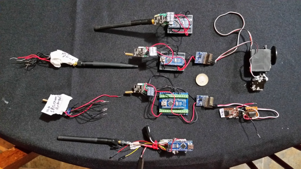
    Some not too positive feedback on this project. The photo says it all. Slow and fiddly progress. Not really any good for the average DIY modeller.

    The middle row shows 4 working RXs . ( A working Mark 1 at the bottom of this row.) The left hand row shows 2  x rf modules that never worked or stopped working.

    So a fairy high failure rate. The fiddly bit is getting the modules to communicate. I have had a lot of problems with binding and doing the configuration from the TX to RX. I have found that using the configurator to flash the software seems to work better than the Arduino IDE. The Hobbyking modules can give similar problems but less often.

    I haven't yet got the DIY module working as a transmitter.

    So my guidance to anyone working on this would be don't expect any easy victories and it is a steep learning curve. I am still some way from trusting a DIY RX in a sub. (Note that I have been using Hobbyking modules very successfully in subs, for several years.)

    So I think that unless commercial organisations can be encouraged to make or continue to make 433Mhz gear we model submariners will have to get used to very elderly 40Mhz gear!

    Connections and parts list details follow:

    Connections for Chinese sourced module (For the Mark 2):

    Arduino-------Level shifter---PCB------S14432
    Not connected            1 GND power supply
    Not connected            2 GPIO0 internal module, launch control foot
    Ard D12*   HV1    PCB no 1      3 SDO 0-VDD V digital output provides a serial readback function of the internal control register
    Ard D11*   HV4    PCB no 2      4 SDI serial data input. 0-VDD V digital input, this pin for 4-wire serial data clock function
    Ard D13*   HV3    PCB no 3      5 SCLK serial clock input. 0-VDDV last month set of inputs. This pin provides a 4-wire serial data clock
    Ard D04*   HV2    PCB no 4      6 NSEL serial interface select input pin,0-VDDV digital input.
    Ard D02     Direct  PCB no 5    7 NIRQ interrupt output pin
    Ard GND   GND   PCB no 6    8 SDN Close the input pin. Input 0-VDDV digital. SDN = 0 in shutdown mode, to GND
    Ard 3.3v     LV      PCB no 7     9 VCC positive supply 3.3V
    Ard +5v      HV

    * Put through voltage level shifter. Add separate 3.3 supply from Arduino.

    Red Led -> D6
    Green Led -> D5

    PPM_IN is D8 (note: RX use D9 as PPM_OUT)
    BUZZER_ACT is A5 (from i2c interface)
    Bind buttons is on A4

    Components:

    SI4432 470MHz 1000m Wireless Module 470M 433mhz Wireless Communication Module
    ( 191674547806 ) (eBay)
    Quantity: 2
    ITEM PRICE:
    £3.00

    SOP14 SSOP14 TSSOP14 to DIP PCB SMD DIP/Adapter plate Pitch 0.65/1.27mm + Pins
    ( 272682553778 ) (eBay)
    No Required: 4
    ITEM PRICE:
    £2.50

    IIC I2C Bi-Directional Logic Level Shifter Converter Module 5V to 3.3V
    puretek-innovations (12579 ) (eBay)

    JHEMCU SPP 8CH Signal Converter Module Support SBUS PPM PWM Output for Receiver
    ID: 1549017 (Banggood UK)
    Price:US$8.76
    david f
    david f
    AMS Treasurer


    Posts : 2395
    Join date : 2010-11-10
    Age : 73
    Location : Cumbria

    UHF radio control  for submarines (openLRS, LoRa, FSK  etc. on 458Mhz and 433Mhz ) - Page 7 Empty Re: UHF radio control for submarines (openLRS, LoRa, FSK etc. on 458Mhz and 433Mhz )

    Post  david f Sat Oct 17, 2020 9:55 am

    A rather more positive report than the last time! The  DIY TX and RX are now both working! A short video showing working DIY TX and RX:

    https://youtu.be/ZX0EVjR85GY

    This is the Mark 1 version which is now working as well as the Mark 2 with a range as good as the Hobbyking equipment (120m +). It is just about ready to use in a sub in the lake  but with Barrow in Furness in Tier 3 coronavirus lock down who knows when that will be.  I hope everyone stays well in Barrow and everywhere else.

    UHF radio control  for submarines (openLRS, LoRa, FSK  etc. on 458Mhz and 433Mhz ) - Page 7 20201012


    Parts list and connection information for the Mark 1 and Mark 2. For anyone trying this go for the Mark 2 version components.  For both, the rf module is soldered onto the SMD adaptor plate (The only tricky bit, but flood with solder and then remove solder with desoldering wick. Then check for shorts with a meter.) This assembly is then connected to an Arduino Nano clone in this case via the level shifter. (Thanks to Jonathan Askey for suggesting this.) Tap off the ppm signal from D9 and feed it through the ppm to pwm convertor and you are done!

    The TX is identical to the RX but with a push button (Arduino A4) and buzzer (to A5) connected to Ground. PPM signal goes to Arduino D8.

    The suggestion by rikiris in his original guide (link below) to test the assembly by flashing it as a TX and using the Spectrum Analyzer is  very useful.

    Don't rely on the Arduino voltage regulator (Vin for supply ) (on the clone anyway?). Provide a good 5v supply which can cope with an amp or two. (I have seen references somewhere that these modules draw high pulse currents.)

    The original instructions put forward by Tim Senecal  are here:

    https://www.instructables.com/How-to-Make-Cheap-DIY-OpenLRSNG-Receiver-RX-433mhz/?fbclid=IwAR3aL_FNy15FYGkSj4VeijFvrjuWLi0L_l5R1yNTD5pSxaRNS09GqOrn8HI

    Original UK sourced module (Mark 1):

    Components:

    SI4432 470MHz 1000m Wireless Module 470M 433mhz Wireless Communication Module UK
    ( 124093501478 ) (eBay)
    ITEM PRICE:
    £7.49

    SOP14 SSOP14 TSSOP14 to DIP PCB SMD DIP/Adapter plate Pitch 0.65/1.27mm + Pins
    ( 272682553778 ) (eBay)
    No Required: 4
    ITEM PRICE:
    £2.50

    IIC I2C Bi-Directional Logic Level Shifter Converter Module 5V to 3.3V
    puretek-innovations (12579 ) (eBay)

    1 GND power supply
    2 GPIO0 internal module, launch control foot
    3 GPI01 internal access module to accept control foot
    4 GPIO2 directly connected to the chip GIIO2 pin

    PCB no 1 not connected
    PCB no 2 to Ard 3.3v 5 VCC positive supply 3.3V
    PCB no 3 to Ard D12* 6 SDO 0-VDD V digital output provides a serial readback function of the internal control register
    PCB no 4 to Ard D11* 7 SDI serial data input. 0-VDD V digital input, this pin for 4-wire serial data clock function
    PCB no 5 to Ard D13* 8 SCLK serial clock input. 0-VDDV last month set of inputs.
    PCB no 6 to Ard D04* 9 NSEL serial interface select input pin,0-VDDV digital input.
    PCB no 7 to Ard(Arduino) D02 10 NIRQ interrupt output pin
    11 SDN Close the input pin. Input 0-VDDV digital. SDN = 0 in shutdown mode, so mode
    12 GND access power ground
    last, connect SDN+GND on SI4432 to Ard GND (yes, 2 hole combined)

    * Put through voltage level shifter. Add separate 3.3 supply from Arduino. (RDF addition)


    New Chinese sourced module (Mark 2):

    Arduino<<<<<Level shifter<<<<PCB<<<<<<S14432
    Not connected                      1 GND power supply
    Not connected                      2 GPIO0 internal module, launch control foot
    Ard D12*   HV1 PCB no 1      3 SDO 0-VDD V digital output provides serial readback function of  internal control register
    Ard D11*   HV4 PCB no 2      4 SDI serial data input. 0-VDD V digital input, this pin for 4-wire serial data clock function
    Ard D13*   HV3 PCB no 3      5 SCLK serial clock input. 0-VDDV last month set of inputs. Provides a 4-wire serial data clock
    Ard D04*   HV2 PCB no 4      6 NSEL serial interface select input pin,0-VDDV digital input.
    Ard D02     Direct PCB no 5   7 NIRQ interrupt output pin
    Ard GND    GND  PCB no 6     8 Connect SDN and GND on S14432 together and then to Ground.
    Ard 3.3v    LV     PCB no 7     9 VCC positive supply 3.3V
    Ard +5v     HV

    * Put through voltage level shifter. Add separate 3.3 supply from Arduino. (RDF addition)

    Red Led -> D6
    Green Led -> D5

    PPM_IN is D8 (note: RX use D9 as PPM_OUT)
    BUZZER_ACT is A5 (from i2c interface)
    Bind buttons is on A4
    This works (RDF)

    Components:

    SI4432 470MHz 1000m Wireless Module 470M 433mhz Wireless Communication Module
    ( 191674547806 ) (eBay)
    Quantity: 2
    ITEM PRICE:
    £3.00

    SOP14 SSOP14 TSSOP14 to DIP PCB SMD DIP/Adapter plate Pitch 0.65/1.27mm + Pins
    ( 272682553778 ) (eBay)
    No Required: 4
    ITEM PRICE:
    £2.50

    IIC I2C Bi-Directional Logic Level Shifter Converter Module 5V to 3.3V
    puretek-innovations (12579 ) (eBay)


    JHEMCU SPP 8CH Signal Converter Module Support SBUS PPM PWM Output for Receiver
    ID: 1549017 (Banggood UK)
    Price:US$8.76


    UHF radio control  for submarines (openLRS, LoRa, FSK  etc. on 458Mhz and 433Mhz ) - Page 7 20201011


    UHF radio control  for submarines (openLRS, LoRa, FSK  etc. on 458Mhz and 433Mhz ) - Page 7 20201016

    The back of the transmitter. Not too pretty  but a gutted Futaba with Phil Green's Arduino version. The instructions and software are all available (My thanks to John Wrennall for finding this and Phil Green for doing all the hard work) at:

    http://www.singlechannel.co.uk/
    (Go to the archive page and and find " P17]  Sketch for 7 channel proportional encoder using the Arduino, with Single-Channel mix

    The trainer plug of (I think) any transmitter will give you ppm output.

    UHF radio control  for submarines (openLRS, LoRa, FSK  etc. on 458Mhz and 433Mhz ) - Page 7 20201018

    I find that the Chrome Configurator works fine for both flashing the openLRS  and configuring the RX and TX and it is much more convenient to just plug it into a USB port. This is the TX configure screen for 458Mhz (UK legal) with the settings I use:

    UHF radio control  for submarines (openLRS, LoRa, FSK  etc. on 458Mhz and 433Mhz ) - Page 7 Tx_con10

    The corresponding RX configure screen:

    UHF radio control  for submarines (openLRS, LoRa, FSK  etc. on 458Mhz and 433Mhz ) - Page 7 Rx_con10


    The ppm inverter suggested by John Robinson to help solve the TX problems in a phone conversation this week. (Sorry I have lost the reference for this version but they are fairly standard.) I later found that I didn't need this but my thanks to John for his help.

    UHF radio control  for submarines (openLRS, LoRa, FSK  etc. on 458Mhz and 433Mhz ) - Page 7 Sbus-i10


    So if you are following this do have a go at ordering and trying this technology. It will not break the bank and it will move you into some new technology which offers a bit more than 40Mhz. The problems I have had in getting this to work are that projects like this with clever hardware and software provide lots of opportunities to NOT work and don't offer much feedback.* You just need to plug away methodically and hope to get lucky! My thanks to my colleagues world wide who have collaborated with this project.

    Later edit: Good news! I have just been re-testing 2 of the failed  rf modules which now seem to be working. I think my comment marked above with * applies.


    Last edited by david f on Mon Oct 26, 2020 10:16 am; edited 6 times in total
    avatar
    tsenecal
    Guest


    Posts : 305
    Join date : 2015-04-01

    UHF radio control  for submarines (openLRS, LoRa, FSK  etc. on 458Mhz and 433Mhz ) - Page 7 Empty Re: UHF radio control for submarines (openLRS, LoRa, FSK etc. on 458Mhz and 433Mhz )

    Post  tsenecal Sat Oct 17, 2020 6:49 pm

    david,

    most modern computerized transmitters will now allow you to indicate which direction the ppm signal needs to be (positive shift or negative shift), but it is nice to know that for older equipment there is a hardware fix.

    some other observations that you can take with a grain of salt.... (this is DIY and very alpha at this stage)

    thingiverse and other 3d modelling sites have objects like this: https://www.thingiverse.com/thing:1691786 that would allow you to bundle up all the TX parts into a usable facsimile of a commercial product.

    all in all i am happy to see your work here, and you have done a very good job testing the waters for the rest of us.

    bravo

    david f likes this post


      Current date/time is Tue Mar 19, 2024 10:42 am