The Association of Model Submariners.

Would you like to react to this message? Create an account in a few clicks or log in to continue.

* THE FORUM FOR ALL THOSE INTERESTED IN BUILDING AND OPERATING MODEL SUBMARINES *


Join the AMS - Registered Forum users can become members of the AMS and it's free ...... To join send an email with your name , address and phone number to amstreasure@googlemail.com


For a guide to past events see the "Shows and Events" section.

Papplewick Pumping Station SUBMARINE Day. 31st March - 1st April 2024.

$$$

&&&

::::

Who is online?

In total there are 8 users online :: 0 Registered, 0 Hidden and 8 Guests

None


Most users ever online was 180 on Tue Nov 05, 2019 6:03 am

Latest topics

» Newbie needs advice!
PIC and Arduino microprocessors - Page 2 EmptyToday at 4:17 am by geofrancis

» Modulated electric fields for submarine communication in a "heads up" from Harry!
PIC and Arduino microprocessors - Page 2 EmptySun Apr 21, 2024 6:09 am by geofrancis

» 868/915 Mhz as a viable frequency for submarines.
PIC and Arduino microprocessors - Page 2 EmptyWed Apr 10, 2024 5:48 am by tsenecal

» Laser cut Robbe U47 conversion
PIC and Arduino microprocessors - Page 2 EmptyTue Apr 09, 2024 3:40 pm by david f

» ExpressLRS - 868/915 Mhz equipment
PIC and Arduino microprocessors - Page 2 EmptyTue Apr 02, 2024 3:27 pm by tsenecal

» Information on camouflage patterns for German seahund
PIC and Arduino microprocessors - Page 2 EmptyFri Mar 15, 2024 4:36 pm by david f

» WW2 mini sub build
PIC and Arduino microprocessors - Page 2 EmptyTue Mar 12, 2024 1:56 pm by geofrancis

» Not the hobby I expected :)
PIC and Arduino microprocessors - Page 2 EmptySun Mar 10, 2024 6:30 pm by cat

» Sheerline gasket material
PIC and Arduino microprocessors - Page 2 EmptyMon Feb 19, 2024 9:24 pm by Michaelc

Statistics

Our users have posted a total of 12448 messages in 1981 subjects

We have 1010 registered users

The newest registered user is Chris Shelley

+6
tsenecal
profesorul
John Wrennall
bwi
Harry.Brash
david f
10 posters

    PIC and Arduino microprocessors

    david f
    david f
    AMS Treasurer


    Posts : 2397
    Join date : 2010-11-10
    Age : 73
    Location : Cumbria

    PIC and Arduino microprocessors - Page 2 Empty Re: PIC and Arduino microprocessors

    Post  david f Fri Nov 06, 2015 2:16 pm

    Hello Marius!

    Nice videos and you make some very good suggestions - so a "steep learning curve".

    I suspect the problem comes when you try to combine libraries in a single sketch. Probably no substitute for a basic grounding in C. (It would be nice to know how others have got on with the Arduino.)

    I will let you know how I get on with the LCD.

    David
    profesorul
    profesorul
    Guest


    Posts : 386
    Join date : 2011-07-03
    Age : 59
    Location : Bucuresti, ROMANIA

    PIC and Arduino microprocessors - Page 2 Empty Re: PIC and Arduino microprocessors

    Post  profesorul Fri Nov 06, 2015 6:22 pm

    THANK YOU DAVID .

    MARIUS
    avatar
    tsenecal
    Guest


    Posts : 311
    Join date : 2015-04-01

    PIC and Arduino microprocessors - Page 2 Empty Re: PIC and Arduino microprocessors

    Post  tsenecal Fri Nov 06, 2015 7:52 pm

    david & marius,

    i have spent a little time lately making two different objects using arduinos.

    1) a ballast tank controller

    2) a sensor "hub"

    the sensor hub has 2 temperature sensors, one voltage sensor, one amperage sensor, a compass, x tilt, y tilt, and depth sensor, and sends the data back to the transmitter by "faking" the data for a "D" series frsky hub, and sending it back through the 433mhz receiver/transmitter module to a Taranis transmitter display.

    david hit the nail on the head. i was limited to a specific set of arduino boards due to the i2c and serial and usb libraries i needed to use to get all the sensors working together, and sending data to the receiver.

    the same thing is limiting what boards i can use with the ballast tank controller, i need to be able to read a specific channel from the receiver, read a pressure sensor, count interrupts from a hall sensor, read two on/off switches, and send servo signals to a speed controller. using the available interrupts without having libraries step on each other limited which boards could be used for that as well. I am hoping to be able to use the same pressure sensor data that the smart ballast controller is using to verify depth as data to be sent back to the transmitter as telemetry, but if the telemetry library interferes, it will be tossed.

    i find that any library that uses timers or interrupts or serial ports will probably interfere with at least one other library....

    Tim
    profesorul
    profesorul
    Guest


    Posts : 386
    Join date : 2011-07-03
    Age : 59
    Location : Bucuresti, ROMANIA

    PIC and Arduino microprocessors - Page 2 Empty Re: PIC and Arduino microprocessors

    Post  profesorul Sun Nov 08, 2015 4:21 pm

    Hy @tsenecal ,

    THANK You for that complex answer !.
    But for me is WAY TOO much ...LOL , ....and I can't even say the Famous replica " English Please" ... LOL ,

    My knowledge in programming with this new invention - Arduino and with programming in general are extremely limited , and You have to imagine that a I am child hoo is just learning to barely crawl away ..... and wheel take long time until get to stand up and talk .
    So for me what are you say is like that Chinese ... LOL .

    If You have time to explain litle by litle about each one of those devices : "...temperature sensors, one voltage sensor, one amperage sensor, a compass, x tilt, y tilt, and depth sensor..." about how did You make them interract with Arduino is great , if Not is OK .

    Actualy I am interested to see and understand how did You made the "ballast tank contoller " first , and then step by step If there is anought time the other things .

    THANK YOU and All the Best

    MARIUS
    avatar
    tsenecal
    Guest


    Posts : 311
    Join date : 2015-04-01

    PIC and Arduino microprocessors - Page 2 Empty Re: PIC and Arduino microprocessors

    Post  tsenecal Mon Nov 09, 2015 12:32 am

    Marius,

    i understand your need to crawl before you can walk. my livelyhood is computer programming, and i have been doing it for 35 years, plus 4 years of college education. programming the arduino takes me back to those very early days, the programming can be very easy, but also very frustrating.

    the only real info you need to understand from my overly detailed reply is that i have two separate arduino gadgets being built. they both require using all kinds of sensors, and different sensors communicate with the arduino in different ways. some very simple, some not.

    the big problem with arduino is that a lot of the extended functionality comes from libraries. code that other people have written, and you can use as if it is part of your program. they wrote it for themselves, and use it by itself. it works fine until you try to use it with another library that some one else ( a third person ) wrote, completely independently from you and the person that wrote the first library. it may use some of the same basic functionality (timers, or interrupts) as the first library, causing a conflict. add to that, different models of arduino have different capabilities. software that runs perfectly fine on one type of arduino might fail completely on a different type of arduino.

    as to the rest of the questions about how i did a specific thing, I plan to do exactly that. i want to document exactly how i built the arduino device that sends the telemetry data from the submarine back to my Taranis, including the code i wrote to do it. the ballast tank controller will come after that.
    david f
    david f
    AMS Treasurer


    Posts : 2397
    Join date : 2010-11-10
    Age : 73
    Location : Cumbria

    PIC and Arduino microprocessors - Page 2 Empty Re: PIC and Arduino microprocessors

    Post  david f Mon Nov 09, 2015 2:00 pm

    Hi Both,

    I still seem to be on a roll with this Arduino, good progress and I only got them on November 5th. (And I'm still leading a normal life - eating, talking, watching TV etc.!)

    The best advice, is always to have a problem you REALLY want to solve otherwise you give up at the start of the  steep learning curve.

    In my case, the problems were solved some years ago - a lipo voltage monitor  and a proportional piston tank controller so this reduces my motivation a bit. These work on PICs and were written in assembler. They did take weeks and months to write and test so I am interested to see if the Arduino makes it quicker and easier.

    First up was the voltage monitor. I used the ReadVoltageMonitor sketch from the Basic examples. I liked the Serial Monitor to put output on your computer screen (In Tools) since it made the Arduino very "talkative" unlike PICs. (I am not going to bother with the LCD yet, as a result.) You would need to put some hardware on this setup - voltage divider etc. It would need voltage alarms triggered in software but that is not too hard - some > functions.

    Next up was to try to combine software for a counter (input from a Hall Switch ) combined with software to measure pwm output from a receiver. These are the inputs needed to do proportional control of a piston tank.

    These went together very easily (see below - but it is a prototype.) and will print a count and a pulse length in millisecs on your computer screen. It will need a lot more work to give a motor on, motor reverse signal for a H Bridge motor switcher but it came together impressively quickly. PulseIn is very powerful and would be immediately very useful as a transmitter + receiver tester.

    On the downside, I suspect that this simple routine would make excessive demands on processor time ( The Hall switch counter routine could do with being interrupt triggered.)

    I've also blown up one of my 2 Nanos - but they will hardly break the bank.

    I still like the comparison of the Arduino with Fast Food though - if it is just what you want at the time, go for it , but don't expect too much!


    // Simple counter from below (David F) combined with pulsein for pwm input

    //https://quarkstream.wordpress.com/2009/12/11/arduino-4-counting-events/

    int state = LOW;

    int lastState = LOW;

    int count = 0;

    int pin = 7; // input digital pin for pwm input. Digital input pin 8 for Hall switch input.

    unsigned long duration;

    void setup() {
     // put your setup code here, to run once:

     Serial.begin(9600);

     pinMode(pin, INPUT);

     pinMode(8, INPUT);

     state = digitalRead(8);
    }

    void loop() {
     // put your main code here, to run repeatedly:
     if (state == HIGH && lastState == LOW) {

       count++;

       Serial.println(count);
       Serial.println(duration);
     }

     lastState = state;

     state = digitalRead(8);

     //PWM measurement (DF)
     duration = pulseIn(pin, HIGH);
    }
    profesorul
    profesorul
    Guest


    Posts : 386
    Join date : 2011-07-03
    Age : 59
    Location : Bucuresti, ROMANIA

    PIC and Arduino microprocessors - Page 2 Empty Re: PIC and Arduino microprocessors

    Post  profesorul Mon Nov 09, 2015 3:45 pm

    THANK YOU @tsenecal ,

    I understand the complexity of the Programming and for know all I want , is to read all the explanations from the forum , watch the tutorials on YouTube and in time to follow some example .
    I looking forward to see what's next .

    Thank You for Your time .

    MARIUS
    avatar
    tsenecal
    Guest


    Posts : 311
    Join date : 2015-04-01

    PIC and Arduino microprocessors - Page 2 Empty Re: PIC and Arduino microprocessors

    Post  tsenecal Mon Nov 09, 2015 5:31 pm

    David,

    everyone seems to start with the pulsein to read pwm from the receiver.

    that is bad form.

    pulsein is a blocking api call, therefore the Arduino can't do anything else while waiting for the pwm signal to change... which is very bad form if you are waiting for something like a hall sensor or a switch to be triggered... say to keep a piston from driving into the dry space of a submarine...


    there is a very good blog that i found, and is the foundation of all my servo and receiver code:

    http://rcarduino.blogspot.com/2012/01/how-to-read-rc-receiver-with.html

    the author of the blog basically uses interrupts for everything, and counts milliseconds to see how long the PWM pulse was.

    you will want to use interrupts for the hall sensor as well, and that is where things start to get tricky. if your arduino only has 2 interrupts,

    and you are using one for the receiver, and one for the hall sensor... what do you use for the 2 end limiter switches? most serial port libraries also use interrupts...


    Arduiono does have a very nice servo library, that makes sending pulses to a servo or ESC very easy... which is what i used for my ballast tank controller.
    david f
    david f
    AMS Treasurer


    Posts : 2397
    Join date : 2010-11-10
    Age : 73
    Location : Cumbria

    PIC and Arduino microprocessors - Page 2 Empty Re: PIC and Arduino microprocessors

    Post  david f Tue Nov 10, 2015 9:59 am

    Hi Tim,

    Yes, I take your point about pulseIn.

    I suppose it is commonly used because it is very simple to use and interrupts can be tricky.

    (It must have applications in systems which are not very processor intensive e.g a servo tester. A piston tank is not that busy either and it occurs to me that my piston tank controller written in assembler works well. That uses an interrupt on the Hall input but the pwm input uses a basic polling routine by Ken Hewitt

    https://www.theassociationofmodelsubmariners.com/t375-pic-and-arduino-microprocessors

    I wonder if the fact that it is in assembler helps? Quicker routines compared with software written in C??)

    We had a discussion on here some years ago about the use of limit switches and we decided against the use of them included in the software. So I use microswitches and diodes in the motor supply line (as shown in Norbert Bruggen's book)

    I think that this is probably the right approach. When faced with a fault that could tear your piston tank apart and sink your sub, it may be best to use a separate control system!

    Many thanks for the excellent link on r/c for the Arduino. That is the way to go.

    David
    avatar
    tsenecal
    Guest


    Posts : 311
    Join date : 2015-04-01

    PIC and Arduino microprocessors - Page 2 Empty Re: PIC and Arduino microprocessors

    Post  tsenecal Tue Nov 10, 2015 6:11 pm

    David,

    this is turning out to be quite the educational thread...

    yep, i think 99% of the people out there use pulsein because it is a single api call, instead of 20 lines of code in three separate areas of the program.

    i understand the use of limit switches as mechanical devices, but by me being stubborn about the brushless motors, one cant cut the circuit with a NO switch cleverly placed in the wiring to the motor, or at least my brain isn't big enough to figure out how to do it, so for me, it is necessary that i use them in software.

    having said all that, i am still only at the testing stage of my ballast tank.  I did, however, get my "hub" tested and working reliably, and consider it to be at a stage where it is "usable"...  but haven't yet decided if it is "useful"...  when running the sub, it isn't always wise to take your eyes off the sub to stare at a little screen.

    the other side of all this code that a lot of people ignore, is how to configure the device. I foresee the ballast tank controller working for both piston and pump/bag style ballast tanks, as well as different size tanks, etc. i see some simple USB communication in my future.

    the joys of having such an insane hobby...
    salmon
    salmon
    AMS Forum Owner


    Posts : 312
    Join date : 2011-09-02
    Age : 64
    Location : Las Vegas, Nevada - USA

    PIC and Arduino microprocessors - Page 2 Empty Re: PIC and Arduino microprocessors

    Post  salmon Wed Nov 11, 2015 2:48 am

    Tim,
    Being a mad scientist helps too!
    Peace,
    Tom


    _________________
    If you can cut, drill, saw, hit things and swear a lot, you're well on the way to building a working model sub.
    John Wrennall
    John Wrennall
    AMS member


    Posts : 157
    Join date : 2011-11-16
    Age : 77
    Location : Leyland

    PIC and Arduino microprocessors - Page 2 Empty Re: PIC and Arduino microprocessors

    Post  John Wrennall Wed Nov 11, 2015 1:40 pm

    Hi all.

    For anyone doing development work on an Arduino Nano, in lieu of a solderless breadboard it is worth considering a Funduino Expansion board.

    http://www.banggood.com/Multi-Function-Funduino-Nano-Shield-Nano-Sensor-Expansion-Board-p-91852.html

    A handful of servo type leads to connect your sensors and a 5V supply and what could be easier...

    John
    david f
    david f
    AMS Treasurer


    Posts : 2397
    Join date : 2010-11-10
    Age : 73
    Location : Cumbria

    PIC and Arduino microprocessors - Page 2 Empty Re: PIC and Arduino microprocessors

    Post  david f Thu Nov 12, 2015 10:40 am

    Hi John,

    That's the one suggested for the TX encoder Arduino is it not? (In which case I have one on order.)

    And Tim. I now understand the need for so many interrupts - you are going to use a brushless motor! I have only ever used brushed motors in piston tanks, so far - partly because of availability and gearboxes etc. (I use the MFA ones.)

    However I am very enthusiastic about the use of brushless propulsion motors now. (More on this shortly)

    David
    John Wrennall
    John Wrennall
    AMS member


    Posts : 157
    Join date : 2011-11-16
    Age : 77
    Location : Leyland

    PIC and Arduino microprocessors - Page 2 Empty Re: PIC and Arduino microprocessors

    Post  John Wrennall Thu Nov 12, 2015 4:47 pm


    Just a thought but has anyone considered using stepper motors for a piston tank.?

    It should be relatively easy to control with something like an arduino, probably no limit switches needed, distinct steps to different depth stages.

    Can anyone comment on the available torque compared with the normal motor and gearbox combination?

    John
    profesorul
    profesorul
    Guest


    Posts : 386
    Join date : 2011-07-03
    Age : 59
    Location : Bucuresti, ROMANIA

    PIC and Arduino microprocessors - Page 2 Empty Re: PIC and Arduino microprocessors

    Post  profesorul Thu Nov 12, 2015 5:41 pm

    I think it is a good idea.
    They are powerful and most of all precise .
    But I don't know if you are made so small as brushed motors and don't know which is the lowest voltage to power them and current consumption .

    That's just my opinion. I don't know much about these motors .
    I have seen they becom used in more and more various applications .  

    MARIUS
    avatar
    tsenecal
    Guest


    Posts : 311
    Join date : 2015-04-01

    PIC and Arduino microprocessors - Page 2 Empty Re: PIC and Arduino microprocessors

    Post  tsenecal Fri Nov 13, 2015 5:58 pm

    tried both a nema 11 and nema 14 size stepper motor on the test ballast tank.

    http://www.omc-stepperonline.com/nema-11-noncaptive-linear-stepper-motor-34mm-body-100mm-lead-screw-t5-x-2-p-205.html

    and

    http://www.omc-stepperonline.com/nema-14-bipolar-stepper-75v-05a-23ncm326ozin-14hs170504s-p-94.html

    i thought the same thing...  they already can be sent specific data to rotate a given number of times.  it basically has the hall sensor to count rotations built into its design.  I even thought the best scenario would be to get one of the stepper motors that has a threaded bore (first link), so that the threaded rod connected to the piston would simply be driven directly through the stepper motor body.

    not good at all.

    compared to a standard motor going through a gear set, the stepper motor is a wimp.  when comparing the specs on a stepper motor, the torque they list is "Holding Torque", meaning, when the motor is stalled, it can hold its position very well.  which leads to the next statement.  to get that torque, the motor is constantly using electricity.  the controller is either sending electricity to one set of windings to make the motor move, or sending electricity to a different set of windings to make the motor hold its position (basically an electromagnet).  this drains the battery much faster than a brushed or brushless motor that is only using electricity when it is moving.

    i even tried using the stepper motor with the same gearbox that i built for the brushless motor.  still no good.  under the smallest load, the motor simply stalls rather than rotating, so even with the gearbox, it would stall 2-3% of the time.  meaning to get an accurate count of the rotations of the final gear, you need magnets and a hall sensor on that gear (not inside the motor).  you end up using exactly the same amount of hardware to make the stepper motor a functional system as you do to make a brushed or brushless motor a functional system. no advantage using the stepper motor.

    one final nail in the coffin for the stepper motor:  when run through the gearbox, it was considerably slower than the brushless motor.  using a 12 volt setup to drive the stepper i used, its maximum speed was 600rpm.  not 600kvm, but 600 rpm.  using a 6 volt battery, the brushless motor's speed is 4800 rpm  it took 2 minutes to move my piston from empty to full using the stepper.  the brushless setup moves from empty to full in 15 seconds.

    as to the question John brought up...   you will still want to use limit switches, solely as an emergency backup.  in a perfect world, a brushed or brushless setup with magnets & a hall sensor shouldn't need limit switches either.   but "belt & suspenders"

    finally, the speed of the stepper really isn't constrained by the voltage sent to it, but by how quickly the controller can "fire" a signal to the motor.  in all setups, i used a separate stepper controller to drive the motor, rather than driving from the arduino.

    https://www.sparkfun.com/products/12779
    avatar
    tsenecal
    Guest


    Posts : 311
    Join date : 2015-04-01

    PIC and Arduino microprocessors - Page 2 Empty Re: PIC and Arduino microprocessors

    Post  tsenecal Fri Nov 13, 2015 6:05 pm

    all in all i was really disappointed in how poorly the stepper worked. but if you look at how the steppers are used in things like the 3d printers, they use bearings and stainless rods everywhere, making for a mass that gets moved with very little friction. i guess a tight fitting o-ring creates a little more friction than a ball bearing.
    avatar
    tsenecal
    Guest


    Posts : 311
    Join date : 2015-04-01

    PIC and Arduino microprocessors - Page 2 Empty Re: PIC and Arduino microprocessors

    Post  tsenecal Fri Nov 13, 2015 6:09 pm

    if i can find some photos i took of the stepper version of the test ballast tank vs the brushless version, i will upload them.
    profesorul
    profesorul
    Guest


    Posts : 386
    Join date : 2011-07-03
    Age : 59
    Location : Bucuresti, ROMANIA

    PIC and Arduino microprocessors - Page 2 Empty Re: PIC and Arduino microprocessors

    Post  profesorul Fri Nov 13, 2015 6:40 pm

    @ tsenecal

    THANK YOU for the useful informations .
    Bring some "light" upon the the subject .

    MARIUS
    John Wrennall
    John Wrennall
    AMS member


    Posts : 157
    Join date : 2011-11-16
    Age : 77
    Location : Leyland

    PIC and Arduino microprocessors - Page 2 Empty Re: PIC and Arduino microprocessors

    Post  John Wrennall Fri Nov 13, 2015 6:56 pm

    Cheers for your information on stepper motors Tim

    Its always good to get feedback like this before needlessly delving deeper into a subject.
    The friction from the O-ring had already given me a few doubts.

    I have already ordered some cheap (£5.00) unipolar motors and controllers for experimentation purposes, looks like they may end up as Christmas decorations.....
    avatar
    tsenecal
    Guest


    Posts : 311
    Join date : 2015-04-01

    PIC and Arduino microprocessors - Page 2 Empty Re: PIC and Arduino microprocessors

    Post  tsenecal Fri Nov 13, 2015 11:06 pm

    John Wrennall wrote:Cheers for your information on stepper motors Tim

    Its always good to get feedback like this before needlessly delving deeper into a subject.
    The friction from the O-ring had already given me a few doubts.

    I have already ordered some cheap (£5.00) unipolar motors and controllers for experimentation purposes, looks like they may end up as Christmas decorations.....


    i did the same thing, thinking the controllers could be used on the better stepper motors. wrong.

    something like these?

    http://www.ebay.com/itm/2pcs-DC-5V-Stepper-Motor-28BYJ-48-ULN2003-Driver-Test-Module-Board-for-Arduino-/321779670958?hash=item4aeb901fae:g:ARcAAOxyBgpSacgM


    they are sitting in a box with all the other stepper motor stuff
    John Wrennall
    John Wrennall
    AMS member


    Posts : 157
    Join date : 2011-11-16
    Age : 77
    Location : Leyland

    PIC and Arduino microprocessors - Page 2 Empty Re: PIC and Arduino microprocessors

    Post  John Wrennall Sun Nov 15, 2015 6:54 pm


    Exactly the same. 5 sets for £9.98 from Ebay

    david f
    david f
    AMS Treasurer


    Posts : 2397
    Join date : 2010-11-10
    Age : 73
    Location : Cumbria

    PIC and Arduino microprocessors - Page 2 Empty Re: PIC and Arduino microprocessors

    Post  david f Sat Nov 28, 2015 1:10 pm

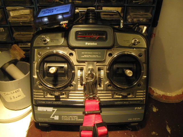
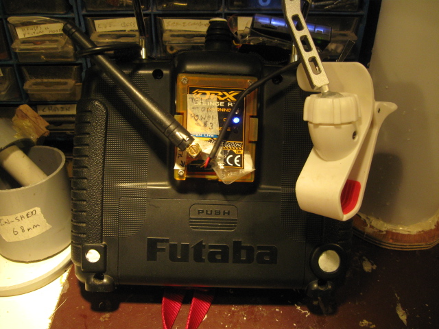
    Well I have just put the Arduino to some useful work - converting one of Brian's 35Mhz transmitters (Futaba Skysport 6A) to 458MHz. (John W showed the way on here in the 458MHz thread.)

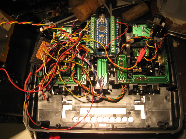
    The Arduino Nano does the work of converting the stick inputs (I have retained the case and pots) and feeding it into an Orange 458Mhz TX module. I used the Funduino breakout board for the Nano for about £2.50 on ebay. This made the connection easier but the pin alignment is a little confusing. My main error was connecting the ppm output to the wrong pin. The ppm signal is easily picked up on a scope (which I am lucky to have) so I could find the right pin.

    I have only just got it working but it looks very promising. I still have to decide what to do about some of the aircraft features e.g exponential. I think I will use the "Flaps" pot for control of the proportional piston tank.

    (Gosh John is posting a reply as I write this. Good point John. Do read the excellent instructions by Phil Green.) I will not post a photo yet because it is a bit of a "rat's nest"- even by my standards!

    Cost of this TX amounts to about £18! I am using the China sourced Nanos which are a bit "like fuses". Two have died already but on the plus side they only cost about £2.50 each. So this is still a remarkably cheap project.

    Many thanks to Phil Green for all his work on this project.
    Phil Green's software follows just bung it in as a sketch in the Arduino Nano:


    // 7 channel encoder by Phil Green

    // Simple, minimal six channel PPM encoder. Four propo, one toggle-switched with servo-slow (ch6), one momentary button  (ch5)
    // Please do not use bootloader, startup delay messes things up and can strip servo gears.
    // Connections:
    // Pots wired between ground and regulated 5v from Arduino. Wipers connected as follows:
    // A0=aileron, A1=elevator, A2=rudder, A3=throttle.  A6=expo, A7=rates. D10=mixer, D11=ch5 button, D12=hip-hop group, (and also ch6 toggle switch)
    // Features
    // Stick calibration - hold button in, switch on, still holding button move sticks and trims to extreme corners. Centralise trims, release button.
    // Variable expo & rates on ch1, 2 & 4. Elevon mixer on ch1 & ch2, 75% aileron, 25% elevator.
    // Flick toggle 3x for range test.  Servo reversing by holding sticks over on power up (saved to eeprom). Servo-slow on channel 6 toggle.
    // Scope trigger on D10.   Thanks to Paul Luby for his expo maths!
    // Phil_G on most forums, philg@talk21.com  http://www.singlechannel.co.uk

    int sw_mix = 10; // mixer switch
    int sw_btn = 11; // pushbutton channel 5
    int sw_tog = 12; // toggle channel 6
    int ppm = 13, ppmPulse = 300, neutralPulse = 1200, raw, flips, ch, calibrated=1, startup=1, stickcalHi[]={0,0,0,0}, stickcalLo[]={1023,1023,1023,1023};
    float ch0val, chtemp, channel[]={1200,1200,1200,1200,1200,1200,8000};  // last is sync
    float lastch6, cchannel6, slow, sweep, rate =0, expo = 0;
    byte reverse[]={0,0,0,0,0,0}, rangetest=0, flip=0;
    unsigned int framecounter=0;

    #include <EEPROM.h>

    void setup()  {
           noInterrupts();
     pinMode(ppm, OUTPUT);
     pinMode(sw_mix, INPUT_PULLUP); // set to OUTPUT for scope trigger
     pinMode(sw_btn, INPUT_PULLUP);
     pinMode(sw_tog, INPUT_PULLUP);
           }

    void loop() {
          while (startup==1 && digitalRead(sw_btn) == 0) {
             // calibrate sticks
              calibrated=0;
              for (int stick=0; stick <4; ++stick) {
                raw=analogRead(stick);
                if (raw > stickcalHi[stick]) stickcalHi[stick] = raw;
                if (raw < stickcalLo[stick]) stickcalLo[stick] = raw;
                }
           }
           if (startup==1 && calibrated==0) {
             for (ch=0; ch<4; ch++) {EEPROMWriteInt(ch*4,stickcalLo[ch]); EEPROMWriteInt(ch*4+2,stickcalHi[ch]);}
             calibrated=1;
             }  
           if (startup==1) {
             for (ch=0; ch<4; ch++) {stickcalLo[ch]=EEPROMReadInt(ch*4); stickcalHi[ch]=EEPROMReadInt(ch*4+2); reverse[ch]=EEPROM.read(ch+16) & 1; }
             reverse[3]=0;   // no throttle reverse for safety
             slow=digitalRead(sw_tog)==0 ?500:-500;  // initial channel 6 value
             }
           
            for (ch=0; ch<4; ch++) {channel[ch] = map(analogRead(ch),stickcalLo[ch],stickcalHi[ch],-500,500); channel[ch] = constrain(channel[ch], -600, 600);}
      channel[4]=digitalRead(sw_btn)==0 ?500:-500;  // channel 5

            if (digitalRead(sw_tog) == 0) {
              cchannel6 = 500;
              if (slow < 500) slow+=2;
              }
            if (digitalRead(sw_tog) == 1) {
              cchannel6 = -500;  
              if (slow > -500) slow-=2;
              }
            channel[5]=slow;
      ch0val=channel[0];

            // check for reversing, stick over on power-up, not throttle though.
           if (startup==1) {
             for (ch=0; ch<3; ch++) {
               if (channel[ch] > 450 || channel[ch] < -450) { reverse[ch] ^=B00000001; EEPROM.write(16+ch,reverse[ch]);}
               }
            }
           
           // end of once-only startup routines
           startup=0;

           // read expo pot
           expo = map(analogRead(A6),0,1023,100,300); expo/=100;
           // read rates pot
           rate = map(analogRead(A7),0,1023,100,10);
           rate/=100;
           for (ch=0; ch<3; ch++) {
             if (channel[ch] <0) {channel[ch]=abs(channel[ch])/500; channel[ch]=pow(channel[ch],expo)*-500; }
             else
             channel[ch]=(pow(channel[ch]/500,expo)*500);
             channel[ch]*=rate;
             }

          // do timed stuff
           if (cchannel6 != lastch6) {++flips; framecounter=0;}
           if (framecounter < 12 && flips >5) {
             rangetest ^= 1; // this flags the 3 flicks 'active'
             framecounter=12;
             }
           if (framecounter > 11) flips=0;
           lastch6=cchannel6;

           // format the frame
           channel[6]=0; // 6th element is sync
           for (ch=0; ch<6; ch++) {
             channel[ch]+=neutralPulse;
             if (reverse[ch] ==1) channel[ch] = 2400-channel[ch];
             channel[6]+=channel[ch];
           }
           channel[6] = 15500-channel[6];
           chtemp=channel[3]; channel[3]=channel[2]; channel[2]=chtemp; // change channel order to Futaba AETR

           if (rangetest==1) {
             channel[2]=700; // throttle low
             if (framecounter==50) {
               framecounter=0;
               flip^=1;
               }
             channel[0]=flip==0 ?800:1600;
             if (ch0val < -50 || ch0val > 50) rangetest=0;
           }
           
           // check if mixer switched in
           if (digitalRead(sw_mix) == 0) {
            channel[0]*=.75;
            channel[1]*=.25;
            chtemp=channel[1];
            channel[1]=channel[0]+600-channel[1];
            channel[0]+=chtemp;
            }

     //send ppm frame, last channel holds sync value
           for (int ch=0; ch<7; ch++) {
             digitalWrite(ppm, HIGH);
             delayMicroseconds(ppmPulse);
             digitalWrite(ppm, LOW);
             delayMicroseconds(channel[ch]);
             }
           if (framecounter<255) ++framecounter;
           
    // scope trigger pin 10, ensure mixer switched off, then temp define as OUTPUT in setup
    //      digitalWrite(10, HIGH);
    //  delayMicroseconds(100);
    //      digitalWrite(10, LOW);
          }

    // This function will write a 2 byte integer to the eeprom at the specified address and address + 1
    void EEPROMWriteInt(int p_address, int p_value)
         {
         byte lowByte = p_value%256;
         byte highByte = p_value/256;
         EEPROM.write(p_address, lowByte);
         EEPROM.write(p_address + 1, highByte);
         }

    //This function will read a 2 byte integer from the eeprom at the specified address and address + 1
    unsigned int EEPROMReadInt(int p_address)
         {
         byte lowByte = EEPROM.read(p_address);
         byte highByte = EEPROM.read(p_address + 1);
         return lowByte + highByte*256;
         }


    Last edited by david f on Sun Nov 29, 2015 2:02 pm; edited 9 times in total
    John Wrennall
    John Wrennall
    AMS member


    Posts : 157
    Join date : 2011-11-16
    Age : 77
    Location : Leyland

    PIC and Arduino microprocessors - Page 2 Empty Re: PIC and Arduino microprocessors

    Post  John Wrennall Sat Nov 28, 2015 1:34 pm

    Phil Green's code just posted by David F is originally from:-

    Code and schematics from the following:-
    http://www.singlechannel.co.uk/

    ARCHIVE tab

    P16 and P 17 for schematic and Arduino C code

    Its definitely worth reading Phil's write-up as the coding includes features such as single channel control which is not normally associated with submarines.
    david f
    david f
    AMS Treasurer


    Posts : 2397
    Join date : 2010-11-10
    Age : 73
    Location : Cumbria

    PIC and Arduino microprocessors - Page 2 Empty Re: PIC and Arduino microprocessors

    Post  david f Sat Dec 05, 2015 12:59 pm

    Some more details on the modified transmitter (One of Brian's) The last photo shows the Arduino Nano sitting up near the top of the case. A bit less of a rat's nest than it was and I have used the breakout board with screw terminals.

    You will need something like a voltmeter continuity tester to identify the wires for the pots (My opening up of my Futaba 9C shows that in modern TXs they have stopped even colour coding leads!)

    I didn't use the trims (which were separate pots) and I used a spring loaded switch for the stick calibration switch, so no need for any extra switches etc.

    PIC and Arduino microprocessors - Page 2 Img_5411

    PIC and Arduino microprocessors - Page 2 Img_5412

    PIC and Arduino microprocessors - Page 2 Img_5415

    PIC and Arduino microprocessors - Page 2 Img_5416

    I am very impressed with the software from Phil Green. Things like the stick reversal routine  work beautifully. (I used the non-reversible throttle output for my piston tank. I didn't want to get full and empty confused!)

    A lot of the "aircraft" features like rates etc. aren't used and you end up with a simple TX. TX's have too many features for model submariners in my opinion. We just need lots of channels.

    So a seemingly very workable TX (not yet pond tested) for about £20. My thanks to Phil Green, Tim S and John W for pioneering all this.

    A nice video of the man himself - Phil Green demonstrating the features. ( He is using it with a 2.4 GHz module rather than a 433/458 MHz module.

    https://www.youtube.com/watch?v=r9ZGZUQClS8

      Current date/time is Fri Apr 26, 2024 12:23 pm