The Association of Model Submariners.

Would you like to react to this message? Create an account in a few clicks or log in to continue.

* THE FORUM FOR ALL THOSE INTERESTED IN BUILDING AND OPERATING MODEL SUBMARINES *


Join the AMS - Registered Forum users can become members of the AMS and it's free ...... To join send an email with your name , address and phone number to amstreasure@googlemail.com


For a guide to past events see the "Shows and Events" section.

Papplewick Pumping Station SUBMARINE Day. 31st March - 1st April 2024.

$$$

&&&

::::

Who is online?

In total there is 1 user online :: 0 Registered, 0 Hidden and 1 Guest

None


Most users ever online was 180 on Tue Nov 05, 2019 6:03 am

Latest topics

» Cheap Arduino Auto leveler
The SubDriver becomes Modular EmptySat May 11, 2024 6:53 pm by 17b

» No reverse on Brushless ESC
The SubDriver becomes Modular EmptyTue May 07, 2024 3:26 pm by geofrancis

» Peral Submarine of 1888
The SubDriver becomes Modular EmptyMon May 06, 2024 11:16 am by david f

» Newbie needs advice!
The SubDriver becomes Modular EmptyFri Apr 26, 2024 1:58 pm by david f

» Modulated electric fields for submarine communication in a "heads up" from Harry!
The SubDriver becomes Modular EmptySun Apr 21, 2024 6:09 am by geofrancis

» 868/915 Mhz as a viable frequency for submarines.
The SubDriver becomes Modular EmptyWed Apr 10, 2024 5:48 am by tsenecal

» Laser cut Robbe U47 conversion
The SubDriver becomes Modular EmptyTue Apr 09, 2024 3:40 pm by david f

» ExpressLRS - 868/915 Mhz equipment
The SubDriver becomes Modular EmptyTue Apr 02, 2024 3:27 pm by tsenecal

» Information on camouflage patterns for German seahund
The SubDriver becomes Modular EmptyFri Mar 15, 2024 4:36 pm by david f

Statistics

Our users have posted a total of 12453 messages in 1983 subjects

We have 1011 registered users

The newest registered user is stig58

3 posters

    The SubDriver becomes Modular

    merriman
    merriman
    Guest


    Posts : 347
    Join date : 2011-10-16
    Age : 75
    Location : Virginia Beach, Virginia

    The SubDriver becomes Modular Empty The SubDriver becomes Modular

    Post  merriman Thu Oct 24, 2019 2:55 pm

    THE SUBDRIVER BECOMES ‘MODULAR’

    Wet-hull type r/c submarines usually employ a removable watertight system to house the devices that need to operate in a dry environment. This Work In Progress (WIP) report chronicles my effort to enhance the utility of my system through modularization.

    WTC is an acronym which originally stood for, Water Tight Container; but today is understood to mean, Water Tight Cylinder. I popularized the WTC through development, production, and sales of the system to the general public. The ‘SubDriver’ name I use today a proprietary device. I claim authorship of the acronym, WTC. Not the concept. For the sake of this discussion WTC, SubDriver, and module describe the same thing.

    The European’s are the real innovators and inventors in this game. The great Nick Burge and others from his side of the world would justifiably challenge any claim on my part suggesting I originated the concept of a removable modular system. I am not. But, I am a dues paying member of the club that, towards the end of the last century, independently devised such systems and foisted them onto the scene.

    OK, clarification of authorship and acknowledgements out of the way. What the hell am I talking about here?
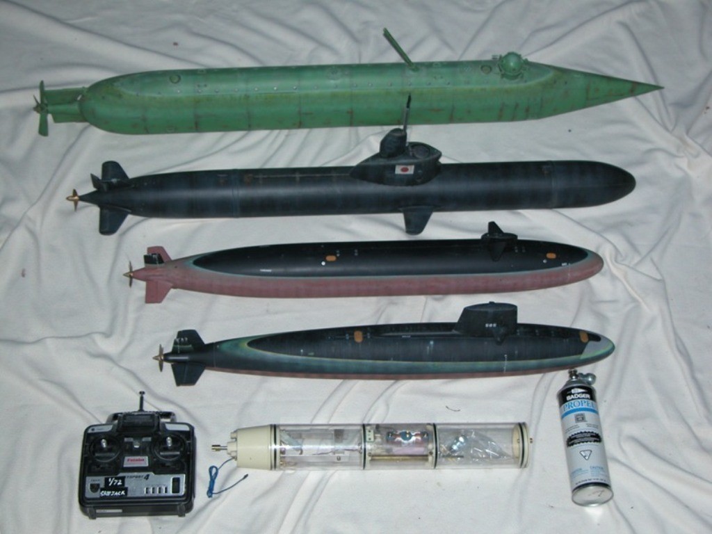
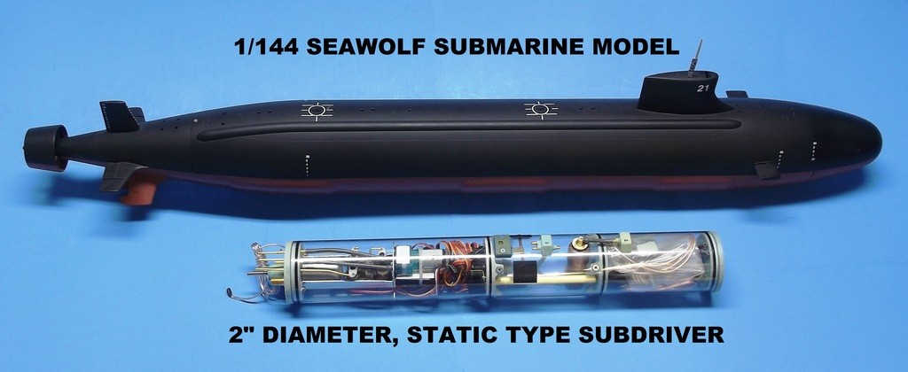
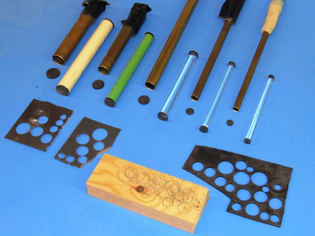
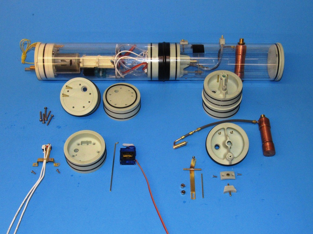
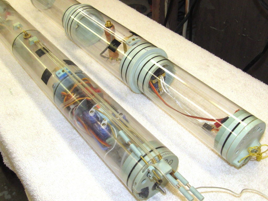
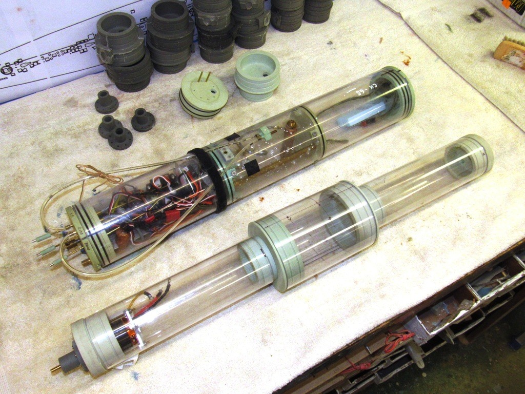
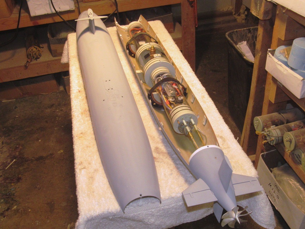
    My WTC started out as a relatively simple, clear, 3” diameter Lexan cylinder; outfitted as a system containing the propulsion, control, and ballast sub-systems needed to operate a wet-hull type r/c submarine. The system is removable from the submarine hull. That ability permitting easy adjustment and repair of the sub-systems, or transfer of the system to another r/c model submarine hull, as illustrated below.

    Note that this single WTC, one of my first, is used to operate any one of these four submarine subjects. The point being, as long as the subjects share propulsion and variable ballast water needs, and can accommodate the system, then one can operate such a fleet with only a single WTC.

    The SubDriver becomes Modular I6EOlc

    However, a major shortcoming with my design is the use of a single length of Lexan cylinder to form the three specifically sized spaces within. For a given WTC of my design there are only so many r/c submarine subjects that fit its operational perimeters.

    Over the decades I’ve sold a significant number of my WTC’s, and through them and other product I have done much to popularize the hobby of r/c submarining throughout the world. In that time the system has changed little in overall configuration.

    The SubDriver becomes Modular WM5oaT

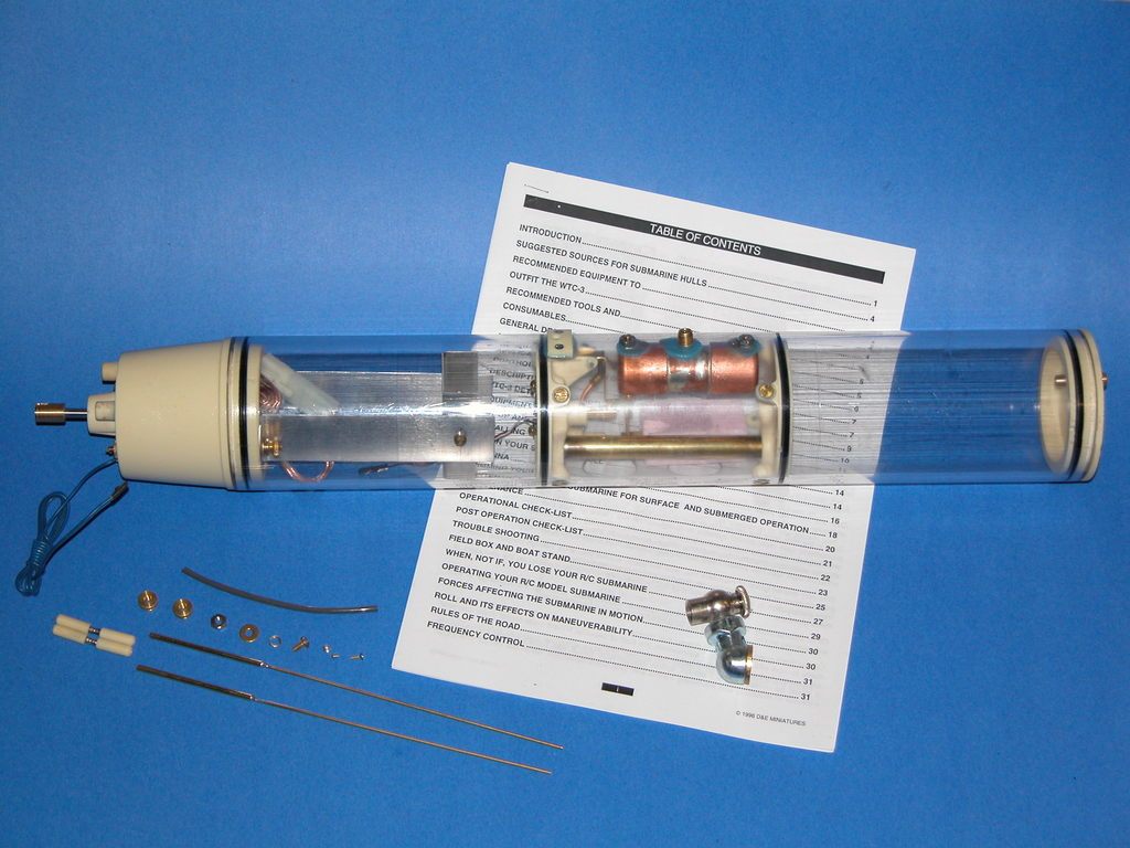
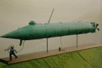
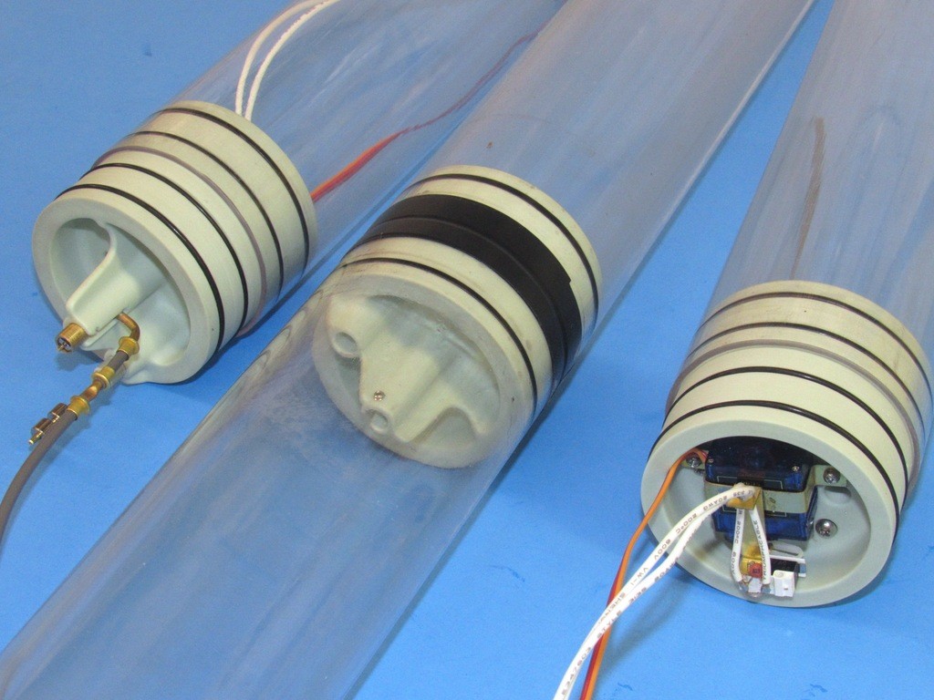
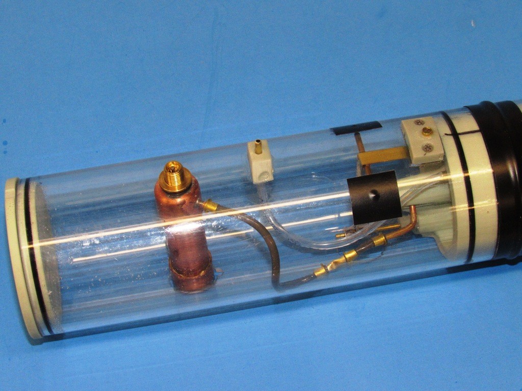
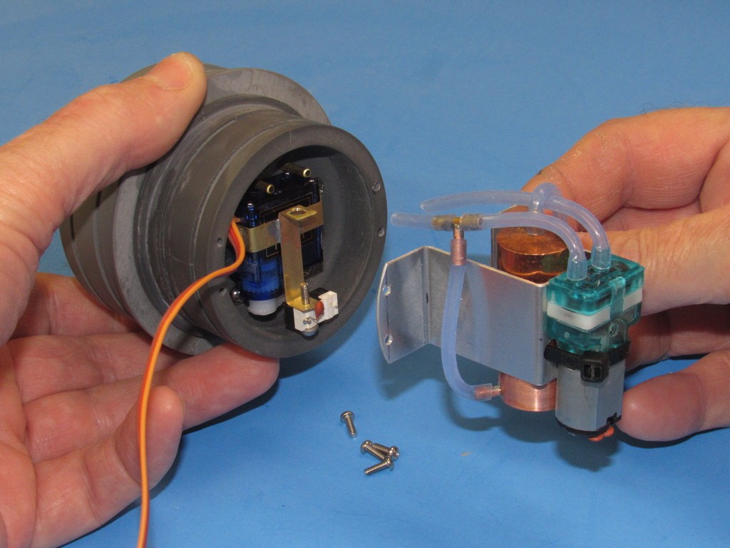
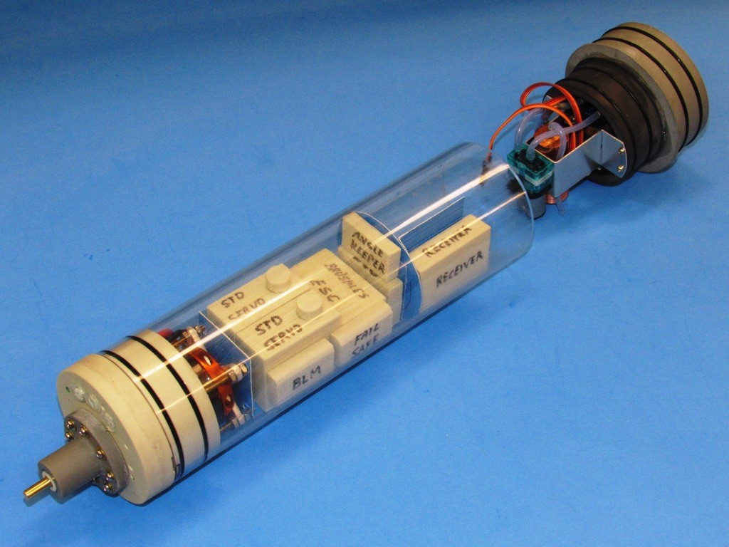
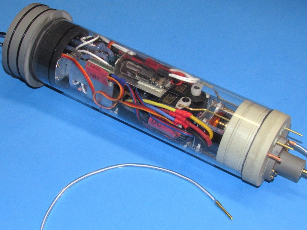
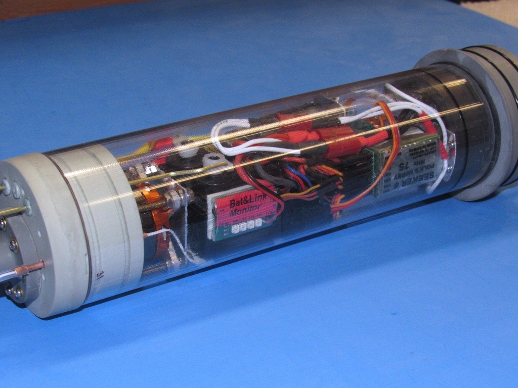
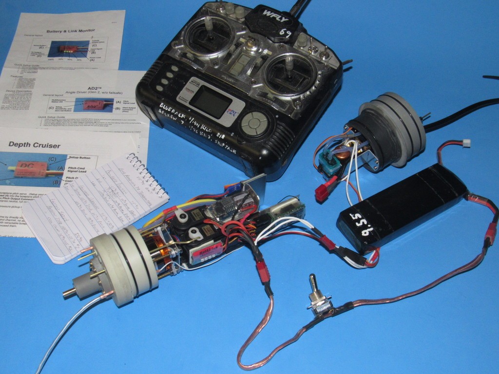
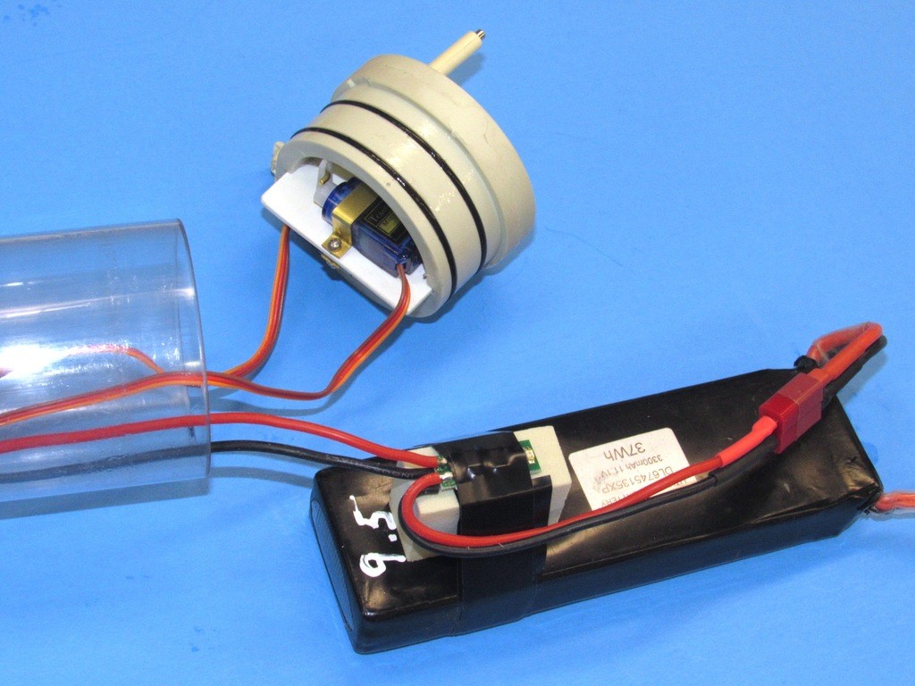
    And that takes us to today. The WTC has matured (in name at least) to, ‘SubDriver’. Pretty much the same internal arrangement, but with the change from a gas type ballast sub-system to one that employs our SemiASperated (SAS) pump-blown ballast sub-system. But with the single Lexan cylinder, this product remains suited to a very limited range of r/c submarine types and sizes. As this picture illustrates – this little SubDriver finds only a few subjects it can be applied too.

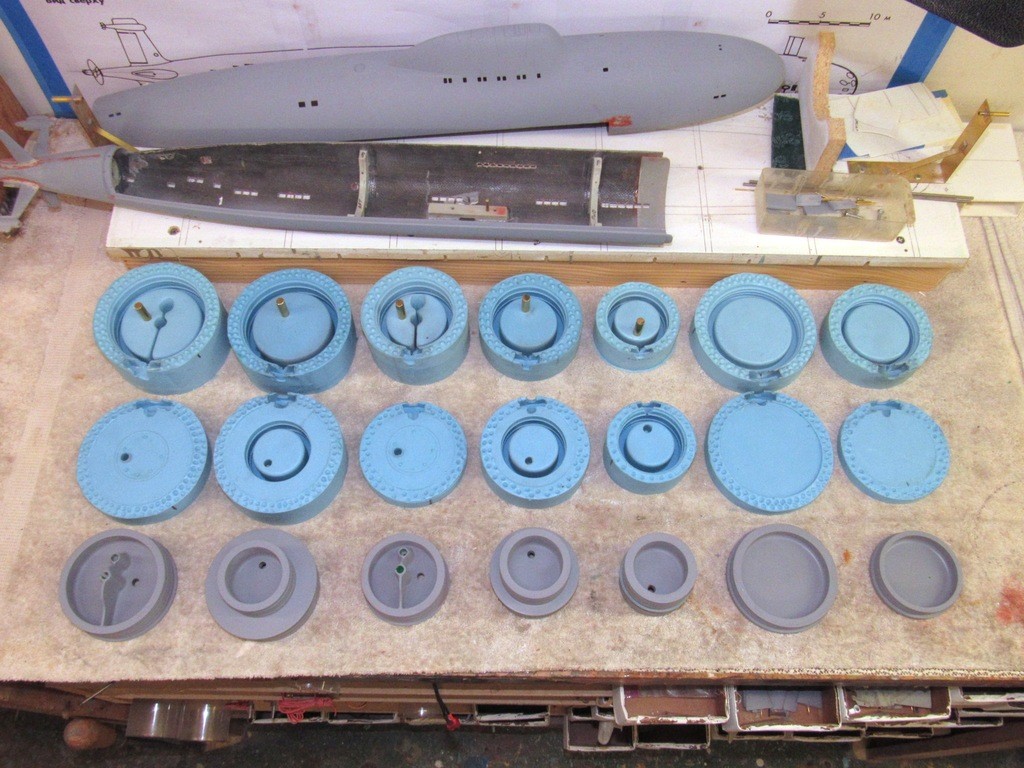
    Illustrating why I’ve had to offer a vast variety of WTC/SubDriver systems each suited for a specific range of r/c submarine subjects. Bob Martin, the owner-operator of The Nautilus Drydock, and my Boss has kindly, but insistently, been pushing me to modularize the system to both reduce his inventory and to make the product more ‘user friendly’. Here, I’m chronicling that effort.

    The SubDriver becomes Modular 3s4sgf

    And less anyone suggests that I’m blissfully charging in with this narrative to exclaim my new invention, please be assured that I know of and appreciate the work of those who inspire me. The previously mentioned Nick Burge is a sterling example: that guy modularized the WTC, and published his efforts long before modularizing WTC’s was cool! I stand on his, and the other greats, shoulders here. I am, and always will be, their attentive student.

    The SubDriver becomes Modular RsKlQA

    The SubDriver becomes Modular OlZfGo

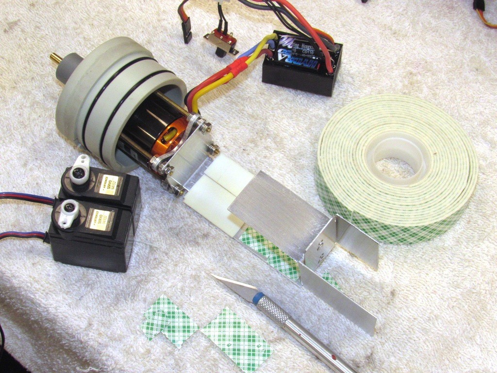
    The objective of the exercise is to cut two lengths of Lexan cylinder, of suitable diameter – one for the after dry space where the propulsion and control devices are; and one, mounted forward of that, to form the ballast tank. These two modules joined by a ‘union’ piece. And by producing different type union pieces we achieve the ability to sleeve different diameter modules into the SD system – the union become the interface point between cylinder sections. This union piece is the key to my method of modularization. The original masters, tooling, and cast parts of the motor-bulkheads, forward closure bulkheads, and other mass-produced parts remain unchanged.

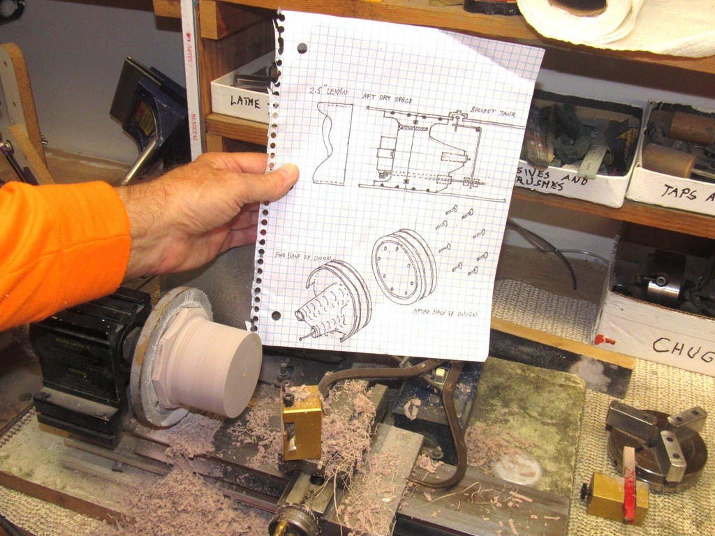
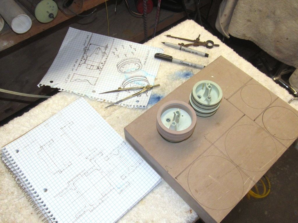
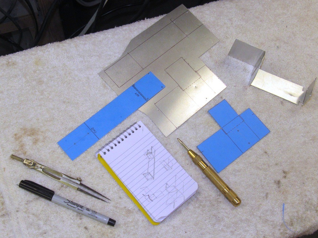
    Work on the union master started with some skull-work and development of a shop-sketch. In this case a union that will permit the joining of two 2.5” diameter lengths of Lexan cylinder. That drawing rendered as proper orthographic and isometric representations of the subject. Enough dope to layout the master and pound it into shape.

    The SubDriver becomes Modular IlDSKZ

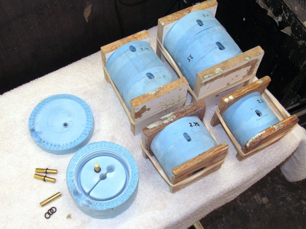
    Note that the union itself will comprise a separable forward and after half – the idea being that I retain the after, dry-space half of the union and gain the opportunity to produce a larger diameter forward (ballast tank) union half – giving me the ability to mate any larger diameter ballast tank module to the existing 2.5” diameter after dry space module.

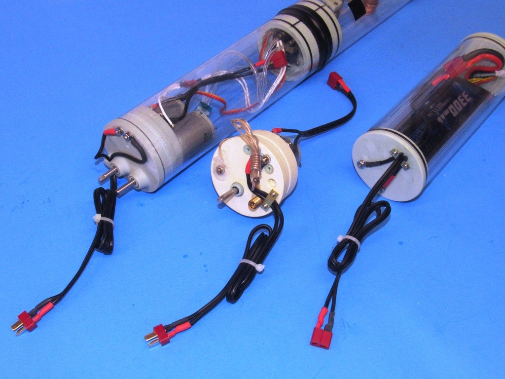
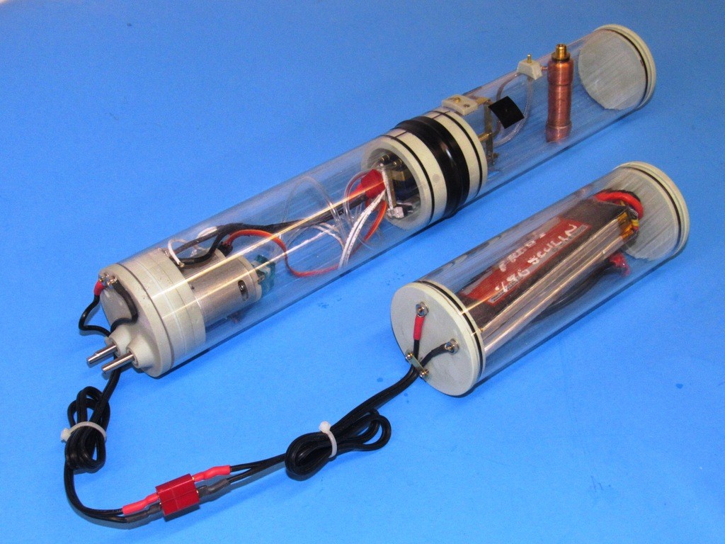
    Bob and I agree that the battery space itself will be a separate length of suitably sized Lexan cylinder, physically removed from the SD proper – its power cable running to the wet side of the SD’s motor bulkhead. That battery module also removable from the model submarines hull.

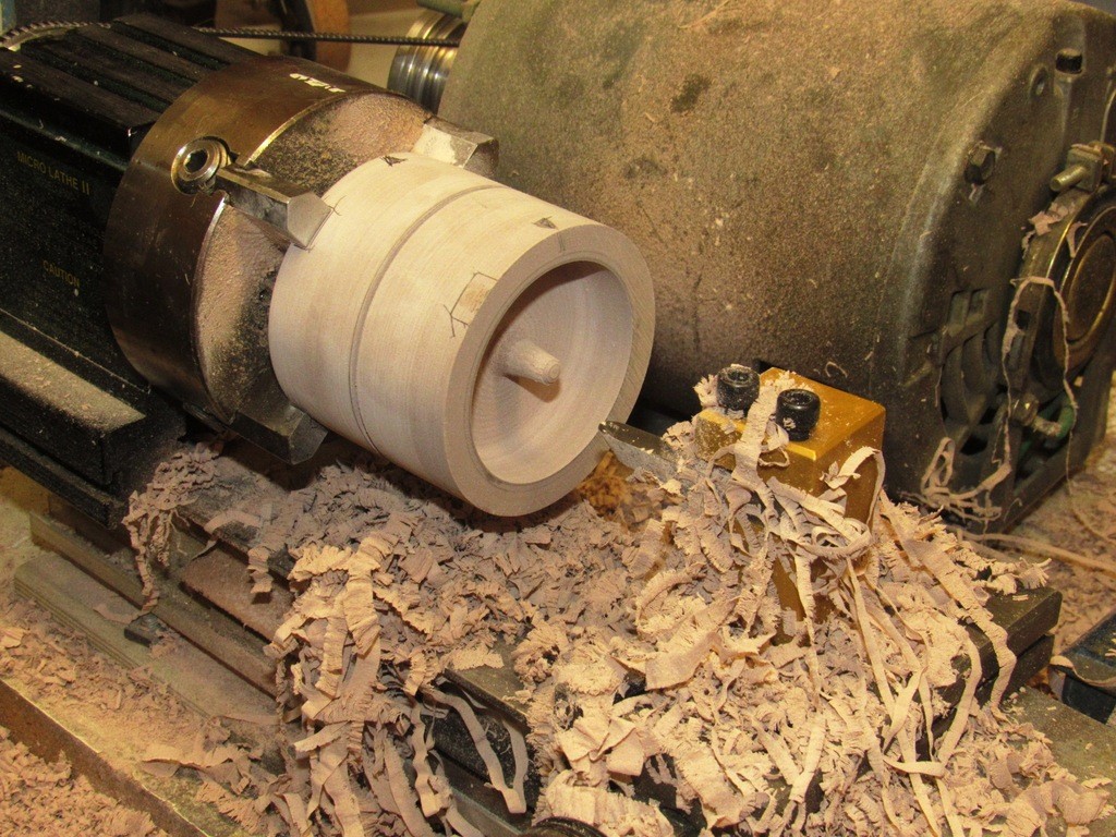
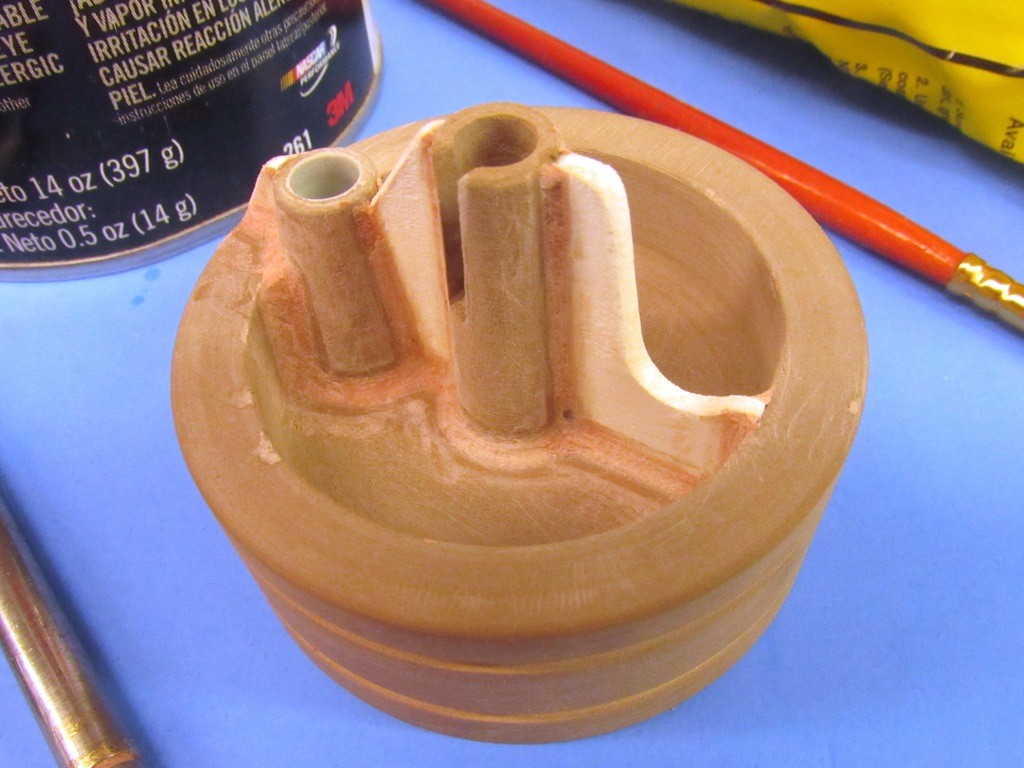
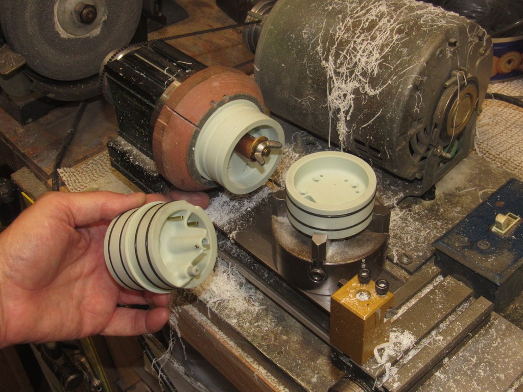
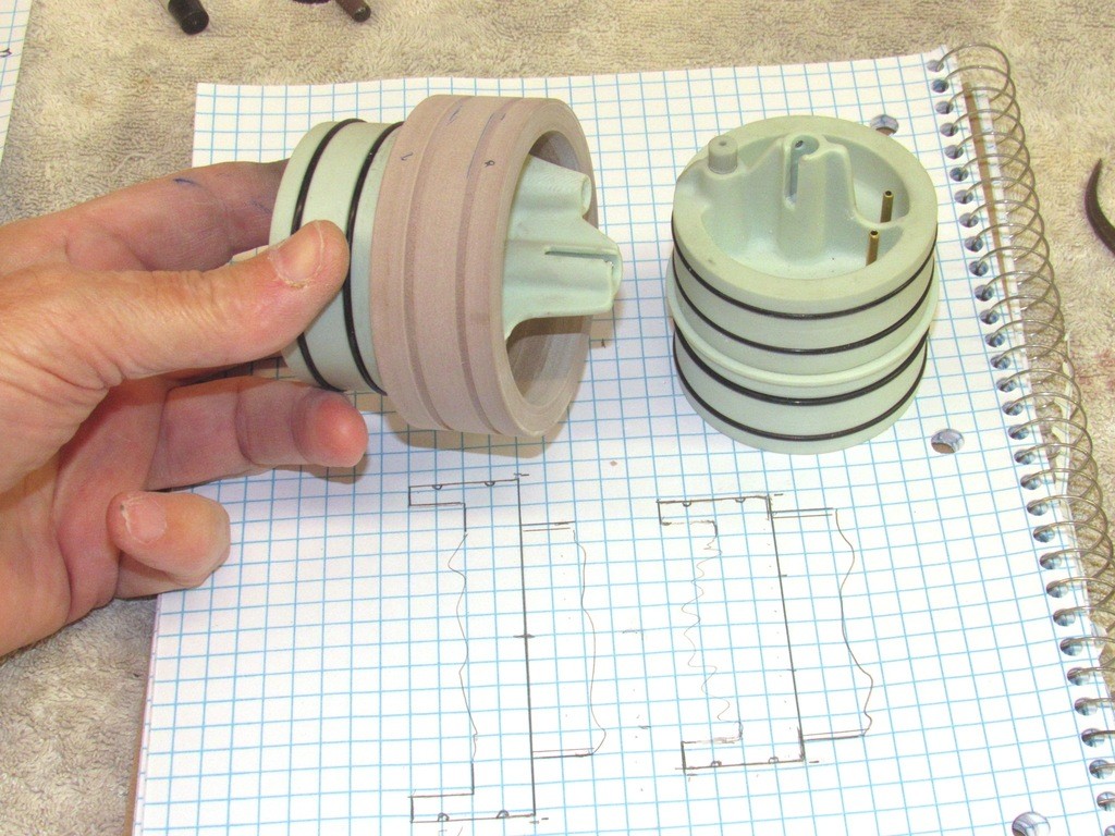
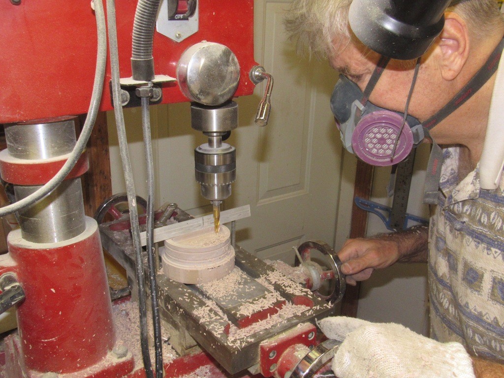
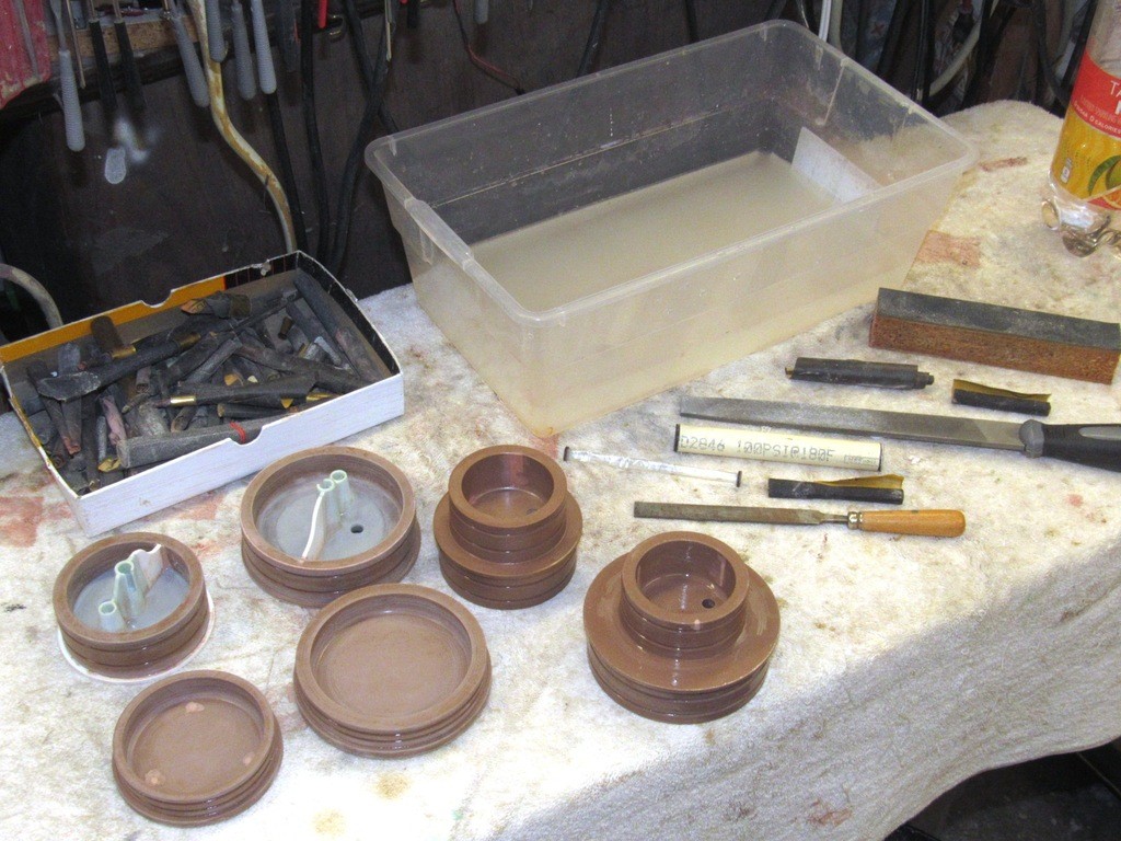
    Work on the 2.5” diameter Lexan cylinder union began by turning a blank of 40 lbs. RenShape to the inside diameter of the cylinder -- oversized a bit to account for tool and casting shrinkage; as well as the sloppy dimensional tolerance evidenced by all sources of extruded Lexan cylinders.

    The SubDriver becomes Modular SDOocX

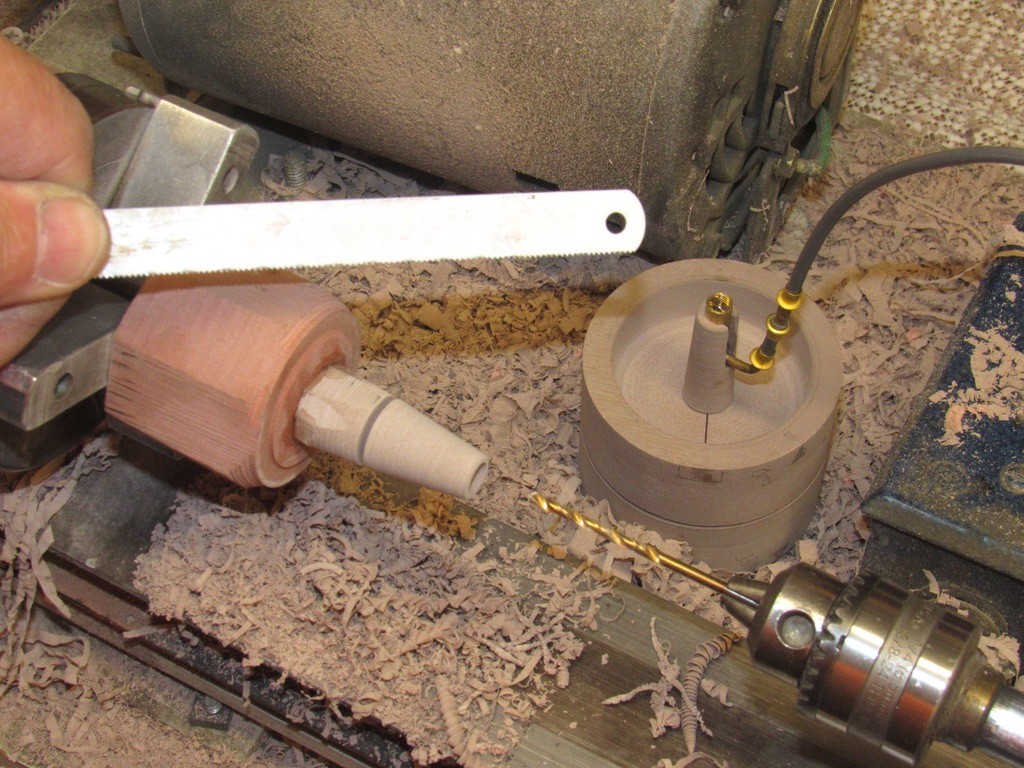
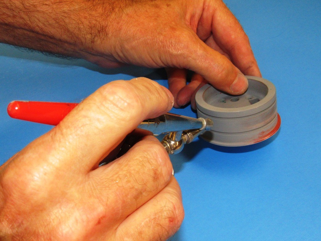
    I started the radial split between forward and after halves of the union right off the bat with a shallow cut with a hack saw blade. Just enough to denote the eventual separation point between the union halves.
     
    The SubDriver becomes Modular YSfvF1

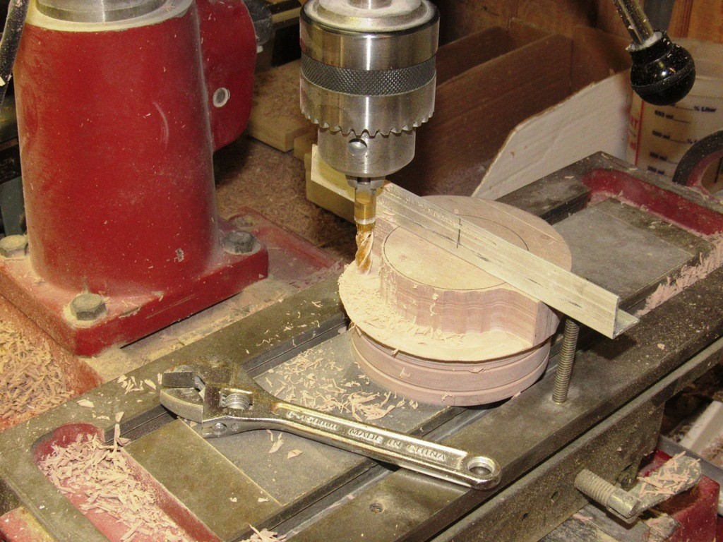
    Note that the blank has been transferred from the face-plate to a proper four-jaw chuck – this so I can turn the work around so I can work both faces while the halves are still attached to one another.

    The SubDriver becomes Modular NoMxdU

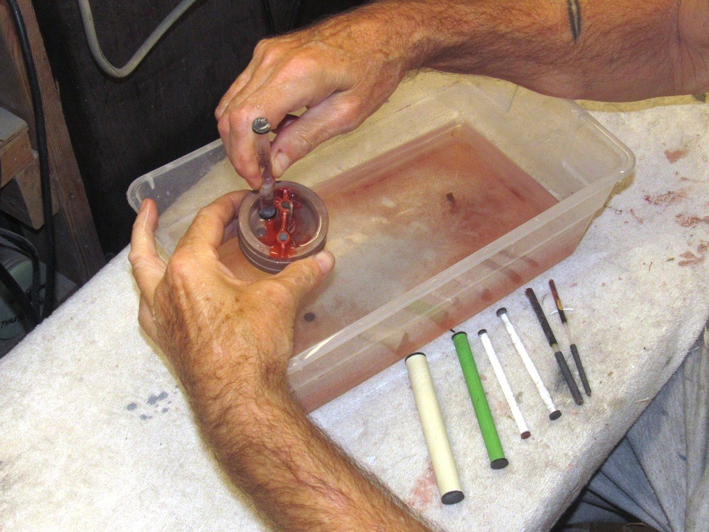
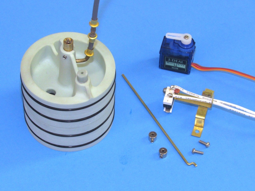
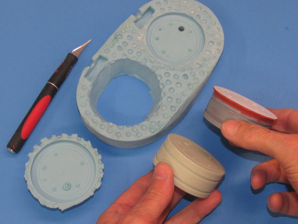
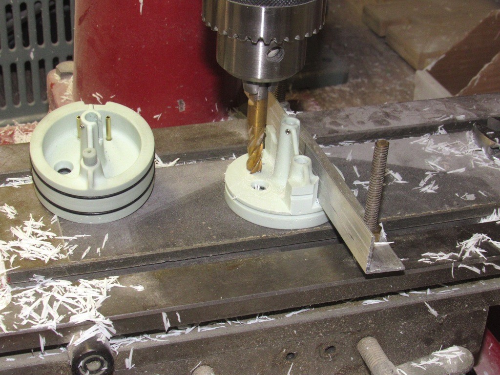
    The ballast tank half of the union being outfitted with the foundations for the ballast servo pushrod seal and emergency ballast blow valve (an optional blow method recommended for open water operations). These foundations temporarily pinned to the union piece so I could affirm non-interference operation of the ballast servo linkage and actuation of the blow valve. If the master can’t be made to operate as designed, then neither will the eventual castings work as intended. Crap in, crap out.

    The SubDriver becomes Modular MLRow5

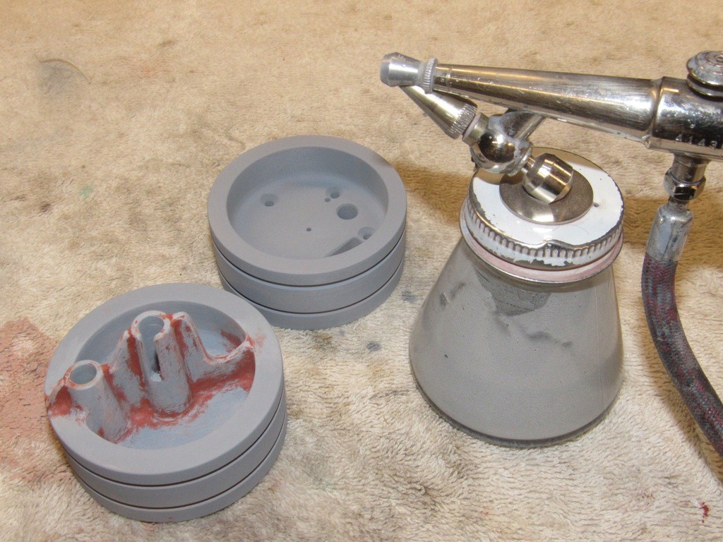
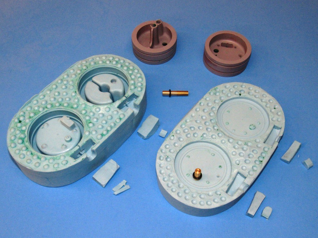
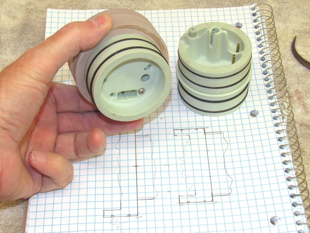
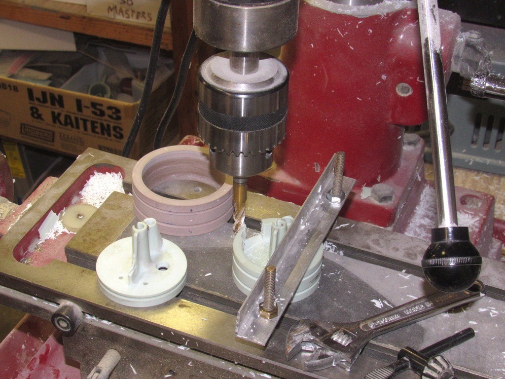
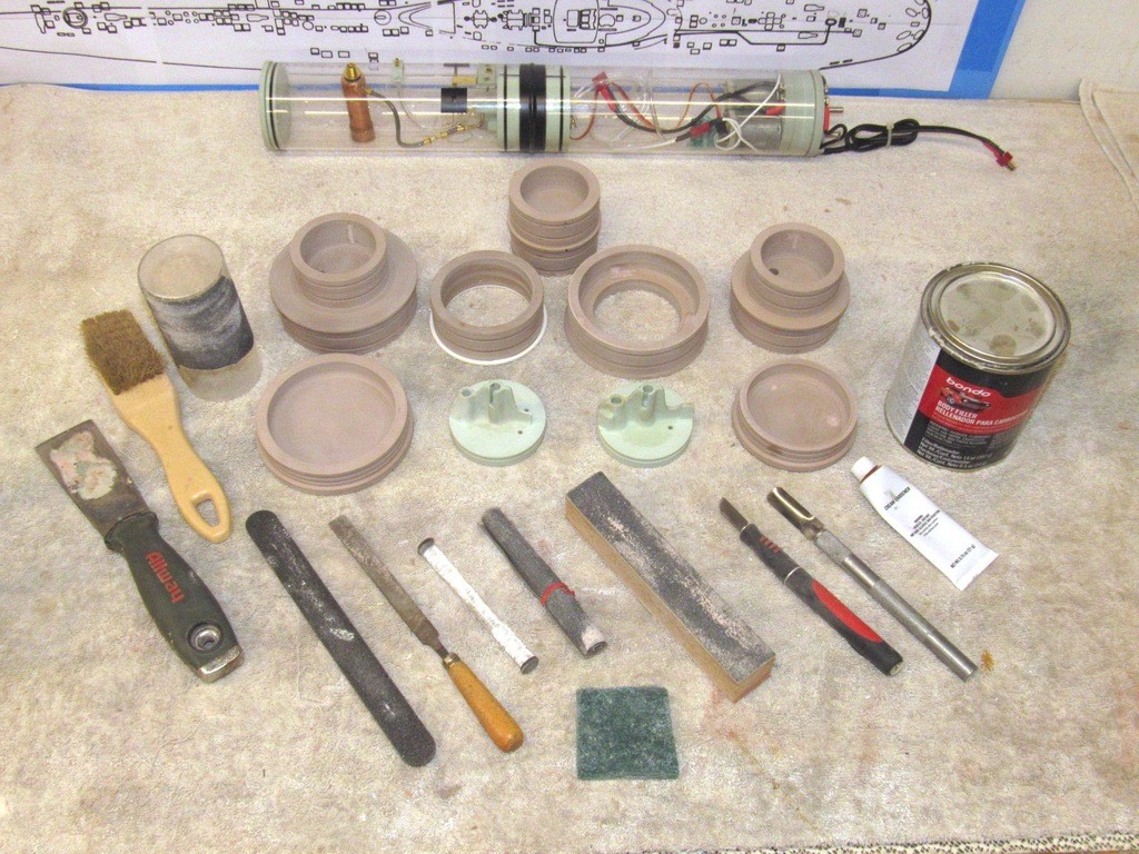
    Here, the union master, mocked up and shown next to a cast resin after ballast bulkhead production part. Note how they share the same seal and blow valve positions and function.

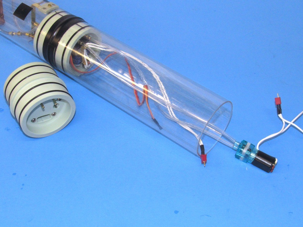
    There is no need for a conduit hole through the union, as the separate battery compartment will provide power to the SD through externally running power cables. There will be no conduit running the entire length of the modularized SD’s ballast tank.

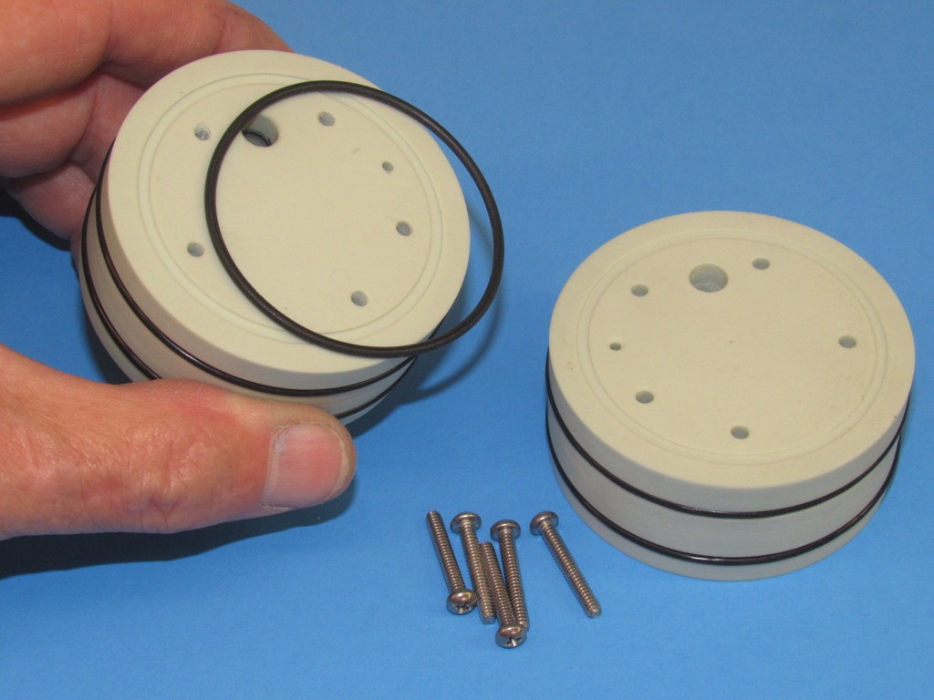
    As there are no mechanical fasteners (only a tight wrap of Electrician’s tape) securing the Lexan cylinders together over the union, I’ve eliminated the occasional problem of cracking of the Lexan -- those fractures originating where fastener holes and fastener pressure cracks the Lexan. No holes, no cracking! Note that a watertight seal between union and cylinders is achieved with O-rings, as is the area between the union halves. The union halves will be held together with eight 4-40 X 3/4” flat-head machine screws.

    The SubDriver becomes Modular YFY2qN
    merriman
    merriman
    Guest


    Posts : 347
    Join date : 2011-10-16
    Age : 75
    Location : Virginia Beach, Virginia

    The SubDriver becomes Modular Empty Re: The SubDriver becomes Modular

    Post  merriman Sat Oct 26, 2019 9:57 am

    Though the radial flanges of this union master are too over-sized to fit the inside diameter of the Lexan cylinders – the over-size to account for later tool and part shrinkage – I laid out the cylinders to give you a better idea of what the union piece is all about: a means of joining two separate lengths of cylinder; the union piece affording the ability to size the after dry space and ballast tank to suite a specific need.

    I’ve mocked-up operation of the union by inclusion of the ballast sub-system servo and its pushrod, and temporarily pinning the pushrod seal and emergency blow valve foundations within the face of the forward union half. If the outfitted master will work, so will the eventual cast resin production unions.

    The SubDriver becomes Modular CUqFYh

    The after dry space side of the union required a little milling to produce a well to provide clearance for ballast sub-system servo bell-crank travel. Other than that the majority of the machining was done on the lathe and drill-press.

    The SubDriver becomes Modular Ubgm7d

    Though what I’m building is a master from which tooling will be made -- from which production union parts will be cast from polyurethane resin -- I do make the master a fully operable device. If I can’t get the master functional, then how can I expect the castings to be functional?

    Case in point is the ballast blow/vent linkage, which is actuated by a little ‘mini’ sized servo. The pushrod travels through both halves of the union and is made watertight at the ballast tank side of the union through a pushrod seal that mounts at the forward end of the pushrod seal foundation.

    Here I’m using a servo-setter to check for unbinding operation of the pushrod through the extreme throws of the servo bell-crank. The machining I did in the above photo was to dig out that square shaped well in which the servo bell-crank travels.

    The SubDriver becomes Modular 4bnYwV

    To the left are the things that fit to the face of the after, dry space side half of the union: the ballast sub-system servo, servo strap with attached low pressure blower limit switch, and pushrod. To the right is the forward ballast tank half of the union which is yet to have permanently attached to its face the emergency blow valve and pushrod seal foundations

    The SubDriver becomes Modular WtPSOf

    Though not envisioned to see much use, I am providing in the union halves a ¼” hole to accept the after end of a conduit – through which power cables would run – if the end-user decides to graft, through another simpler version of the union, the forward battery space directly to the forward end of the ballast tank.

    Most users will elect to simply plug the conduit hole and house the battery in a separate length of cylinder.

    Note the marking stencil, made from clear acetate sheet, used to guide me as I drilled out the holes for the five machine screws used to compress the two union halves together when assembled.

    The SubDriver becomes Modular XLqb7n

    Cutting in the O-ring grooves to the radial flanges of the union. The watertight seal between Lexan cylinder and union will be accomplished with the aid of two O-rings for each half of the union. Right after this operation I sawed the union into its respective halves.

    The SubDriver becomes Modular BaNOFR

    A recent addition to the SAS type ballast sub-system was the substitution of a mechanical limit-switch for the electronic motor controller that formerly operated the low pressure blower. You see the limit switch mounted to the servo securing strap. As the servo bell-crank travels to the ‘blow’ position it closes the limit-switch which completes the circuit to the motor, starting it pumping air (either coming from the SD dry spaces or through the broached snorkel) into the ballast tank, pushing the water out.

    You see to good advantage in this picture the square milled well that provides clearance for the servo bell-crank when it travels to the extreme ‘vent’ position.

    The SubDriver becomes Modular NPbAV8

    The two halves of the union will be secured with five (initially I planned on eight, but things got too tight within the union for that) 4-40 flat-head machine screws. I have yet to cut in the O-ring grooves that will make things watertight within the tight space between the two union halves.

    The SubDriver becomes Modular 6orHOB

    Within the forward half of the union .080” Sintra sheet was used to make the three gussets that support and improve eventual resin flow through the tool used to cast the resin production parts. Once glued in place the base of the gussets as well as the two foundations were given Bondo fillets. I used one of Mom’s old dapping tools as a fillet tool, assuring a constant radius fillet all around. After wet-sanding the fillets with a twist of #100 grit sand paper I coated the work with Nitro-Stan air-dry touch-up putty. And after that dried I wet sanded the work with a twist of #220 sand paper. This made the work ready for primer.

    The SubDriver becomes Modular Xvzu3U

    The SubDriver becomes Modular BTFRSq

    merriman
    merriman
    Guest


    Posts : 347
    Join date : 2011-10-16
    Age : 75
    Location : Virginia Beach, Virginia

    The SubDriver becomes Modular Empty Re: The SubDriver becomes Modular

    Post  merriman Sun Oct 27, 2019 10:04 pm

    Specialized sanding tools were used to reach into the flat and vertical surfaces within the two union master halves: One type of tool for the flat surfaces, a sanding disc; the other for the vertical, a sandpaper wrapped dowel or twist of sandpaper.

    By the way, whenever possible, I wet-sand the work. The water helps to keep abraded material from clogging the surface of the abrasive.

    The SubDriver becomes Modular HJaykw

    The right side of this union master half (the ballast tank side) has already been sanded using the specialized tools. The left side is still in the raw, its puttied surfaces yet to be worked with abrasives. What complicates this particular sanding job is the need to preserve the small radius fillets between foundations, gussets, and the flat internal face of the master. That’s why the sandpaper discs are secured to a piece of rubber sheet – giving it the flexibility to ride up the fillet radius, following its contour, not cut into it.

    The SubDriver becomes Modular TK9VZV

    This is how the sanding tools for deep flat surfaces (and surfaces that transition from horizontal to vertical through fillets) are made. A round handle (shank, if you will) has glued to its end a disc of soft rubber, to the face of that rubber disc is glued a disc of sandpaper. Each of these tools has a disc of #200 grit sandpaper at one end, and a disc of #220 sandpaper at the other. Note how the edge of the rubber and sandpaper disc extends slightly past the diameter of the tools shank – this permits the flexible rubber to bend, and along with it the sanding disc, permitting the sandpaper to ride up and conform with the curvature of a fillet. Neat!

    Note the brass-tube cutters used to punch out the rubber and sandpaper discs.

    The SubDriver becomes Modular P2tBft

    Some of the sanding tools I used to smooth out the Bondo and Nitro-Stan filler and putty. The surfaces at right-angles to one another, joined with tight radius fillets presented a special challenge when it came time to abrade them smooth.

    The handle/shank of each tool is round, be it wood dowel, PVC tube, or acrylic rod. Whatever is at hand.

    The SubDriver becomes Modular Wuxhyn

    The touch-up putty was carefully abraded back and primer applied. Problem areas got more putty and sanding, and priming – the process continuing till everything was nice and pretty.

    The SubDriver becomes Modular 1XYzRP

    Steel wool and 3M abrasive pads are excellent abrasives that get into tight radius corners and deep wells, such as presented by the two union master halves. Where fingers can’t reach, hemostats can. These fine abrasives used only on the primer. The course work gets the sandpaper treatment!

    The SubDriver becomes Modular 2dsdQv

    A quick job of buffing the cavities within the master halves was done by spinning a hunk of steel wool, at slow speed, with the aid of a variable speed electric drill.

    The SubDriver becomes Modular ER3rny

    The two halves of the union master being prepared for creation of the rubber resin casting tool. This will be a two-piece tool. Footing the masters in a layer of clay secures them in place. Additionally the pliable clay is the perfect medium for pressing the dimples that will give form to the indexing network at the flange line between the two eventual tool halves.

    The containment dam for this first half of the tool is simply a wrap of masking tape.

    The SubDriver becomes Modular TpORIx

    So, how much expensive rubber to prepare for a specific job? A great cheat to determine the exact volume of rubber needed is to substitute a liquid, like water – pouring in the amount needed to cover the masters, and then pouring the water into the container you’re going to mix the rubber in and marking off the waterline within. That waterline mark denoting how much catalyzed rubber you need.

    Second best cheat, and less messy, is to substitute rice for the water. That’s what I’m doing here.
    RTV platinum cured silicon mold making rubber is expensive. Rice ain’t.

    The SubDriver becomes Modular KggmQo

    Here I’m pouring the first half of the rubber tool. The two-part tool will give form to the cast resin production union parts. This single tool produces both the forward (ballast tank side) and after (dry space side) of the union.
    Before pouring the catalyzed and thoroughly mixed RTV rubber over the masters – that process invariably folding in a lot of little air-bubbles into the mix, the mix was de-gassed by subjecting it to a hard vacuum for several minutes.

    The SubDriver becomes Modular PhcrNV

    Deep Diver (Fred)
    Deep Diver (Fred)
    AMS member


    Posts : 268
    Join date : 2010-11-07
    Age : 75
    Location : Peacehaven East Sussex

    The SubDriver becomes Modular Empty WTC

    Post  Deep Diver (Fred) Tue Oct 29, 2019 4:19 am

    Hi Merriman

    Having just read your post I see that you have given Nick a lot of the credit for the WTC, yes Nick did do some of the engineering on one of the first WTC that I know off, but the idea came from a Friday night meeting some of us had at Alf Blakes shop.

    Some time after this meeting Bernie, Nick and my self were at Bernie's talking thing over with regards to WTC's and that was when Bernie came up with the idea of using rain water piping as a WTC, as Nick had had his own engineering company in South Africa he said that he would do all the engineering work, and from this one of the first WTC came about.

    As Nick and Bernie are no longer with us there is no way that this can be ratified.

    Fred

    merriman
    merriman
    Guest


    Posts : 347
    Join date : 2011-10-16
    Age : 75
    Location : Virginia Beach, Virginia

    The SubDriver becomes Modular Empty Re: The SubDriver becomes Modular

    Post  merriman Tue Oct 29, 2019 6:46 am

    Deep Diver (Fred) wrote:Hi Merriman

    Having just read your post I see that you have given Nick a lot of the credit for the WTC, yes Nick did do some of the engineering on one of the first WTC that I know off, but the idea came from a Friday night meeting some of us had at Alf Blakes shop.

    Some time after this meeting Bernie, Nick and my self were at Bernie's talking thing over with regards to WTC's and that was when Bernie came up with the idea of using rain water piping as a WTC, as Nick had had his own engineering company in South Africa he said that he would do all the engineering work, and from this one of the first WTC came about.

    As Nick and Bernie are no longer with us there is no way that this can be ratified.

    Fred


    Fred,

    Thank you so much for fleshing out the brief WTC history I presented in the preamble of my WIP article -- an important element concerning the ground-breaking developments Mr. Burge presented in his article so many years ago. Now we know a bit more of the story.

    I appreciate your enhancement of the record. It's a strong belief of mine that attribution should be given at every opportunity in order to credit those people who move the ball forward, no matter the endeavor or degree of contribution. Thank you for the above additional information on the subject, Fred.

    This is history, and we are all honor bound to acknowledge the good works of those who came before us as well as our peers.

    David
    Student of the Craft
    Deep Diver (Fred)
    Deep Diver (Fred)
    AMS member


    Posts : 268
    Join date : 2010-11-07
    Age : 75
    Location : Peacehaven East Sussex

    The SubDriver becomes Modular Empty Re: The SubDriver becomes Modular

    Post  Deep Diver (Fred) Tue Oct 29, 2019 9:33 am

    Nick was a very good Engineer and he did come up with some good and some bad ideas for the time, and yes with his engineering back ground he did help workout some of the problems that came up now and again, but at times he did take the credit for others ideas, but don't some of our politicians do this if they can get away with it.
    merriman
    merriman
    Guest


    Posts : 347
    Join date : 2011-10-16
    Age : 75
    Location : Virginia Beach, Virginia

    The SubDriver becomes Modular Empty Re: The SubDriver becomes Modular

    Post  merriman Wed Oct 30, 2019 8:19 am

    After completing the second half of the rubber tool, the halves were pulled apart, the masters removed and put into safe storage, and sprue and riser cavities cut into the top of each cavity through which the casting resin would be poured. The square-shaped riser cavities serve as reservoirs that provide enough make-up resin within the tool to back-fill the cavities which have entrapped air -- air that is only crushed into solution during tool pressurization, a point in the process where I can’t get at the tool to pour in the make-up resin.

    Note the O-ring equipped brass rod. This serves as a core piece within the forward half of the union cavity. Once a casting is removed from the tool the core is pulled out, leaving an encapsulated internal O-ring at the center of that bore -- the O-ring there to make watertight the after end of a conduit.

    The SubDriver becomes Modular PuFle6

    Before closing the two halves of the tool and pouring in the catalyzed polyurethane casting resin the internal cavities and flange faces of each tool half are given a good spray coating of mold/part release silicon – the preferred agent here is Mann ease release 200. I buy it by the case! This agent is not only good for resin production work, but is also the perfect barrier between silicon rubber elements during tool fabrication.

    After spraying in the Mann 200, which minimizes any chemical interaction between the RTV rubber and casting resin (extending tool cycle life), I sprinkle on a significant amount of corn-starch or talc powder within the tools cavities, temporarily assemble the tool, shake and bang it around a bit, open it up and dump what powder that failed to cling to the sticky part-release agent onto the shop floor (that act often accompanied by Eleanor’s non-approving ‘look’). The hydroscopic powder, clinging to the cavities surface does two things during the casting process: First, it pulls any moisture (there’s always water in the air) away from the cavity surfaces. And the powder acts as a wick to pull resin into tight confines; spaces within the tool cavities that otherwise would become footholds where air bubbles would reside after the resin is introduced. Such air bubble would manifest as voids on the casting, marring the surface finish of the part.

    The preparatory work out of the way the tool halves are assembled and clamped tightly closed with the aid of strongbacks and rubber bands. And I’m ready to pour resin.

    The SubDriver becomes Modular A8ShlJ

    Casting resin is mixed and poured into the two sprues of the tool, filling the cavities and risers within. The tool is quickly transferred to a pressure pot, which is buttoned up and subjected to at least one atmosphere of pressure; this pressure maintained during the resin state change from liquid to solid, about a twenty-minute process when using the ‘quick-cure’ Alumilite polyurethane casting system.

    The SubDriver becomes Modular DeMB8L

    And the result: two cast resin halves of the union piece. From this point the sprue-riser elements are sawed off, the screw and pushrod bores finished on the drill press, the forward (ballast tank) half of the union tapped to accept the five 4-40 securing screws, the pushrod seal bore deepened, the emergency blow valve bore deepened, an O-ring inserted between the union halves and the unit assembled, and the union is turned on the lathe to achieve a light interference fit between union radial flanges and inside diameter of the Lexan cylinder sections the union joins.

    The SubDriver becomes Modular JMjuQq

    My good buddy, Kevin Rimrodt, during a recent visit noted that I forgot to provide the forward face of the after dry space union half with a projecting flange to prevent hydrostatic pressure from pushing the union aft in the cylinders as the SubDriver is subjected to any meaningful depth of water.

    Duh! Yes, Kevin. I’m an idiot.

    I’ll modify the after half of the master and use that to correct the tool to produce castings with that flange. Thank, Kevin. Good catch... and get that self-satisfied grin off you face!

    Anyway, when you study the below photo just imagine I have that preventer flange in place. This shot shows how things look when the cylinder halves are made up to the assembled union. Holding the cylinder sections in place against pulling apart or rotating is a tightly wrapped piece of Electrician’s tape between the two.

    The SubDriver becomes Modular TgTeQY

    An O-ring watertight seal near the perimeter of the inboard faces of the union halves keeps water away from the pushrod, conduit, and fastening screw bores that run through both halves.

    The SubDriver becomes Modular RDjcqC

    After the O-ring is seated in the grooves of the hand-held union halves, the five securing screws are inserted and tightened down, compressing the O-ring till it affects the watertight seal between the two halves.

    The SubDriver becomes Modular 9E80g1

    As there is such a sloppy tolerance of diameters of Lexan cylinders marketed today I produce the union raw casting with an outside diameter considerably more than any cylinder I’m going to purchase. This necessitates a lathe-turning of the union piece to be a light interference fit for the specific Lexan cylinder I’m dealing with at the moment.

    The ballast sub-system servo, its bracket (with mounted LPB limit-switch), and pushrod make up to the after face of the dry-space half of the union. The pushrod passes through both halves of the union and, at the ballast tank side of the union, emerges through a watertight seal where it makes up to the other elements of the vent valve and emergency blow valve, linkage.

    The SubDriver becomes Modular Ruoz6y


    merriman
    merriman
    Guest


    Posts : 347
    Join date : 2011-10-16
    Age : 75
    Location : Virginia Beach, Virginia

    The SubDriver becomes Modular Empty Re: The SubDriver becomes Modular

    Post  merriman Sun Nov 03, 2019 10:02 am

    OK, I’ve finalized how the union piece between two lengths of Lexan cylinder interfaces the devices within. I kept things simple by making it a 2.5” diameter-to-2.5” diameter union. Owing to the unions design feature of being split into two halves, I can exploit the major advantage of the union: its ability to sleeve different diameters and/or lengths of cylinder (module) together to form a single system.

    But, first let’s look, with some detail, on how the union goes together; and how that union mounts the devices that attach to the after and forward faces.

    In background is a Modularized SubDriver (MSD). I have omitted the separate battery WTC for clarity. The after module (the after dry space) contains the propulsion, control, and some of the SAS type ballasts sub-system devices. The forward module (the ballast tank) is a ‘soft tank’ in that it is always subject to ambient water pressure and contains the mechanics that operate the vent valve atop the tank. Also seen in the ballast tank is the emergency ballast blow sub-system -- an option for those who operate in open water.

    In foreground are the two halves of a union with the devices that attach to each.

    Between the assembled MSD and the exploded union halves are (to the left) two union halves ready to be joined with their five securing machine screws. Note the o-ring between the halves. And (to the right) an assembled union ready to be outfitted with devices -- this union ready to join two modules together.

    The SubDriver becomes Modular ShsHyB

    This shot of our current 2.5” SAS type SD. Note the external plumbing, in the form of two cylinder mounted manifolds and the flexible induction and discharge hoses. So exposed, these external hoses present a likely point of failure. The MSD eliminates the external plumbing, placing all within the two modules, out of harms way.

    Also illustrated here is the major shortcoming of the MSD’s union: an increase of overall MSD length as compared to the short-of-length internal after ballast bulkhead of the standard SD design. However, that extra length is more than compensated for exploiting the unions ability to attach a larger diameter ballast section – for a given ballast tank volume, the overall length of a MSD with an enlarged ballast tank cylinder is significantly shorter than a SD of constant diameter.

    The SubDriver becomes Modular 3OK33U

    Prototyping affirms that the mechanics dreamed up on paper, on the toilet, or during a fevered skull-session with peers actually works in the physical universe; prototype is the stark reality of what works, and what does not work.

    Case in point: when I showed off the initial configuration of the union, my r/c modeling buddy, Kevin Rimrodt (always delighted to catch me in an error!) pointed out that I failed to provide a means of keeping the union from being pushed aft into the dry space by pressure exerted on the ballast tanks side of the union as the MSD experiences greater depth. He squarely put his finger-of-doom on a potentially catastrophic design error.

    Shit!

    I had to equip the after half of the union with a ‘preventer flange’; a ring that would butt up against the forward circular edge of the dry space Lexan cylinder. The alteration of the prototype RTV tool done with relative ease, but only after I modified the after half of the union master to incorporate the preventer flange.

    The SubDriver becomes Modular BWY7gu

    Only the forward face of the after union master was re-worked. A .095” thick disc of polystyrene was glued to its forward face. The fix was quickly addressed with putty and primer, then used to modify the existing rubber tool to produce the ‘improved’ parts.

    The SubDriver becomes Modular G4MT3t

    The offending portion of tool cut out, it was reassembled with the modified master installed, and a new batch of rubber mixed, de-aired, and poured through the hole in the strong-back. After the new rubber had cured, the tool was opened up, the master removed, and the tool used to produce the improved union parts.

    The SubDriver becomes Modular PKUFVC

    The cast resin unions are produced with an outside diameter significantly larger than that of the Lexan tube. I’ve done this to account for the very wide tolerance of diameter between different manufacturers and lots of product on the market.

    I employed a modified face-plate as a specialized lathe holding fixture and a standard four-jaw chuck to hold the work as I refined the diameter of the union radial flanges to suit a specific inside diameter of Lexan tube.

    The SubDriver becomes Modular NlthGP

    As the MSD routs the Low Pressure Blower (LPB) plumbing internally, through the union, I’ve eliminated most of the external flexible hose runs that were sometimes problematic with the old versions of our SAS type SD’s.

    Note that the induction and discharge hoses from the LPB terminate at brass nipples set into the union. The discharge line dumps air directly into the ballast tank. The induction line continues on the wet side through a hose that makes up to the top mounted induction manifold. From atop that manifold another length of hose runs up to the top of the models sail where it makes up to the snorkel head-valve.

    The SubDriver becomes Modular Doynwt

    I’ve retained my style of ballast sub-system linkage to open and close the ballast tank vent valve. However, there has been an active and very slick offering of alternative vent valve linkage and location at the Nautilus Drydock forum. I regard these as concepts worthy of exploration at a later date.

    The single manifold glued atop the ballast tank routs the induction line that originated at the top of the submarines sail, down into the horizontal induction nipple set within the union, and on into the LPB.

    I included an emergency gas blow bottle, hose, and blow valve in the MSD prototype to insure that this optional installation does not interfere with the other devices within the ballast tank.

    The SubDriver becomes Modular JgE8lo

    With the MSD battery power enters the after dry space through the motor bulkhead. Here are two examples of the different type motor bulkheads I developed for the 2.5” cylinder: One a single-motor, single-shaft; and the other a two-motor, two-shaft motor bulkhead. There are other type motor bulkheads, but these are illustrative of how I make up the power cables to the devices within the MSD.

    To insure watertight integrity, I use pass-through brass threaded studs through the resin bulkheads to pass the current from battery to MSD devices. The power cables are common 18-gauge two-conductor ‘zip-cord’. I favor Deans connectors between the MSD’s motor bulkhead and battery WTC power cables.

    Note that strain-relief brackets are employed to prevent pulling force being presented to the points where the power cables make up to the studs.

    The SubDriver becomes Modular Xfqsgn

    This is how power is routed from the separate battery WTC to the MSD.

    To make things water-proof (kinda) I coat over the connectors at the studs with RTV sealant. The Deans connector male and female conductors (particularly the positive conductors) are coated with silicon grease before they are made up and the cable ends of the Deans connectors are encapsulated with RTV sealant.

    Yes, with use water gets into the connectors and wicks into the conductor wire. Water is insidious! But, that is easily addressed every couple of years by replacement of the cables. No big deal.

    The SubDriver becomes Modular ZsumDe


    merriman
    merriman
    Guest


    Posts : 347
    Join date : 2011-10-16
    Age : 75
    Location : Virginia Beach, Virginia

    The SubDriver becomes Modular Empty Re: The SubDriver becomes Modular

    Post  merriman Fri Nov 08, 2019 5:51 pm

    Before the mid-day break for my hideous nap I got this much done converting a 2.5"-to-2.5" pre-production union casting into a 2.5"-to-3" union. I turned a new RenShape radial flange for the step-up required, using the core of a ballast tank half of a 2.5" union for the innards of this pre-production master.

    Anyway, here's how far I got this morning:

    The SubDriver becomes Modular YmHKhQ

    The SubDriver becomes Modular VskuEZ

    The SubDriver becomes Modular JD4X3v

    The SubDriver becomes Modular VuqHOY

    The SubDriver becomes Modular Em5QlR

    Later I'll produce a step-up union for a larger, 3.75" cylinder.

    David
    merriman
    merriman
    Guest


    Posts : 347
    Join date : 2011-10-16
    Age : 75
    Location : Virginia Beach, Virginia

    The SubDriver becomes Modular Empty Re: The SubDriver becomes Modular

    Post  merriman Tue Nov 12, 2019 5:28 pm

    It’s one thing to come up with a clever innovation on an old concept – maturing the WTC to a proper modular system being discussed here as example – but it’s another thing to knuckle-down and get on with the donkey-work of actually making the items that will comprise the new system.

    You’re looking at about two-hundred-dollars worth of 2” thick, 40 lbs. per-cubic-foot, pattern making medium. Most of it soon to be reduced to chips on the shop floor. God’s answer to pattern makers, this extremely dense polyurethane foam is so much superior to the Kiln-dried, carefully selected pattern maker woods used almost exclusively a half-century ago. Sugar Pine was my favorite, but all that timber has long been pulled from the bins, completely replaced by the synthetics. Thank you chemical-scientists!

    No grain. No pitch. No drying and cracking over time. RenShape takes to all adhesives, and its high pH sets off CA glue in record time. If RenShape could only cook!

    Here’s the one I prefer for most of my detail work (the less dense stuff requires extensive filling to get a good surface finish, so I use that version only as floatation material or a back-up to a GRP skin).

    https://www.freemansupply.com/products/machinable-media/renshape-modeling-and-styling-boards/renshape-450-medium-density-modeling-board.

    ‘Measure twice and cut once’, as the old Carpenter’s saying goes. And that double-check philosophy starts with a carefully prepared set of orthographic shop drawings, to the scale of the work, and oversized to account for tool and casting shrinkage (that fudge-factor more art than math, I can assure you!).

    The SubDriver becomes Modular Fl2LgV

    I had already made a master, a tool, and some castings of the 2.5” ballast tank half of the 2.5-to-2.5 union. Now has come the time to make like units for the 3” and 3.75” ballast tank union halves. To save myself effort I simply took the core of the 2.5” castings and married them with 3” and a 3.75” radial flange. To ready these cores I milled away the 2.5” radial flanges on the mill as seen here.

    The SubDriver becomes Modular Ez64BG

    Flat bottom work is easily secured to the milling machines cross-feed bed with a simple L-section aluminum strong-back held down with two jacking screws – holding fixture 101. To enhance the friction between work and bed I glued a big piece of sandpaper atop the bed.

    I’m grinding away the radial flange of the original 2.5” diameter after union half. That work has already been done, as seen with the milled union half to the left. The objective is to insert these cores into larger diameter, RenShape radial flanges. One is for the 3” diameter ballast tank. The other is for the 3.75” diameter ballast tank.

    The SubDriver becomes Modular Cm0ZTH

    Here I’m turning a larger diameter radial flange on the lathe. I’m holding a core that will insert within the radial flange, that core containing the foundations and pass-through holes needed to operate the vent valve and (if installed) emergency blow valve.

    The SubDriver becomes Modular WIjYiQ

    This is the end-game for the two ballast mechanism cores: use them as inserts into the larger diameter radial flanges.

    Important safety note: only idiots ware long-sleeve shirt, ties, apron strings tied at the front, and gloves around powerful rotating machine tools! First lesson in shop-class: “Machines don’t care” and, “Machines cut metal and flesh with equal enthusiasm!”

    Yes, sometimes I’m a careless idiot. And sometimes … I pay the price, and got the scars to prove it! Not battle-scars. No! Idiot scars.

    MACHINES DON’T CARE!

    Want some reinforcement? Check out this video (have a puke-bucket handy), https://youtu.be/lxD7f2zCG40

    The SubDriver becomes Modular SG9t70

    RenShape is easy to cut but quickly dulls high-speed steel. I found it more expedient to do the rough-cuts on the mill and to finish off the round-work on the lathe. Typically a blank was turned to the outside diameter on the lathe then transferred to the mill and the internal cavity roughed out.

    Notice the Michael Jackson glove-look (I was getting blisters from spending two days driving cross-slides, that is why I’m warring the damned thing).

    STUPID!

    Every time I look at the pictures of me operating heavy rotating machinery like this I cringe! (In the caring, and caressing voice of Escape From New York’s villain, A-number-One, as shop-class instructor: “WHAT DID I TEACH YOU!!!!”).

    God-damned! Sometimes I’m such a stupid dumb-ass!! And after seven-decades I still have all my fingers! Amazing.

    The SubDriver becomes Modular Si55NJ
    merriman
    merriman
    Guest


    Posts : 347
    Join date : 2011-10-16
    Age : 75
    Location : Virginia Beach, Virginia

    The SubDriver becomes Modular Empty Re: The SubDriver becomes Modular

    Post  merriman Tue Nov 26, 2019 3:12 pm

    Before I once again get bogged down in the minutia of union and bulkhead pattern and tool making, let me remind you of the objective here:

    The creation of a sub-system of various unions and bulkheads that permits the quick, easy, and fastener-free means of assembling different diameters of Lexan cylinder to form a single, purpose built Modularized SubDriver – a MSD suited for a specific shape of r/c submarine hull with a ballast sub-system sized for that particular model. If the positive features of the modularized SD do not strike you immediately, I will later summarize them for you.

    Examine the photo below. It illustrates the basic differences between the old, constant diameter SD with its many fasteners and sloppy external SAS plumbing; and the new modularized SD showing off the fastener free unions between different diameter Lexan cylinders, varied diameters, and no external plumbing.

    And now, back to the shop!

    The SubDriver becomes Modular Hx7Unj

    Most the gross grinding away of RenShape, as I worked the masters, was done on the milling machine. Once I pulled the work out of that nasty Machinist’s version of a wood-chipper I transferred the work to the lathe to finish shaping. Note the use of a simple aluminum L-section strong-back and all-thread jacking screws to hold the work down tight on the mills bed. KISS.

    I’m not at all shy about drilling and taping holes, welding, or bolting things onto the bed, foundation, spindle, or drip-pan of my machine tools if doing so serves my needs; hand and machine tools can and will be modified to adapt them to my specific wants. I run the show here. Not Dremel, Black & Decker, Chicago Machine or Vigor.
    Secure from rant.

    The SubDriver becomes Modular ZHXAL4

    The union and bulkhead masters nearly completed. I still have to insert the forward union ballast mechanisms into the RenShape 3-inch and 3.75-inch radial flanges.

    Some of the abrasives used to improve the finish of the masters on display here. Bondo was used to fillet the ballast mechanisms inserts and radial flanges.

    In background is a 2.5-2.5 MSD, showing that a constant diameter SD is still possible if the right union is employed between the after dry space and ballast tank cylinders.

    The SubDriver becomes Modular CYRUww

    The union and bulkhead masters were given a thin coating of West System epoxy laminating resin. I cut the catalyzed resin a bit with lacquer thinner to make it flow on a bit easier with a brush. The work was left to cure hard for twelve-hours.

    The SubDriver becomes Modular Fb2dtA

    At this point the 3 and 3.75-inch diameter forward union halves received their ballast mechanism innards which were CA’ed in place. I poured on catalyzed epoxy to fillet between inserts and the large radial flanges. Another twelve hours for that to cure hard, then all masters were wet-sanded with various #400 grit sanding tools to rough up the surfaces to insure good bonding of the first primer coat.

    The masters were given three coats of primer, sanding between each. They were then mounted on molding boards, containment damns erected, and the first half of the RTV silicon rubber tools poured.

    The SubDriver becomes Modular TjSGIF

    Here I’m pouring the second half of the rubber tools that will be used to produce cast resin union and bulkhead parts.

    The SubDriver becomes Modular UdWBIe

    Each union type (ballast equipped and basic) and bulkhead had its own dedicated two-piece rubber tool. The masters used to create these tools are in foreground. Note the 11/32” brass rod cores inserted into those unions that would receive an o-ring which would later make watertight the conduit that would run the length of the ballast tank.

    The SubDriver becomes Modular ZcNfBv

    It’s not enough to provide just a simple sprue hole (the path the resin takes from mixing cup to interior cavity of the tool) when dealing with a tool that takes a significant amount of resin to fill it. A ‘riser’, a reservoir if you will, is incorporated in the sprue to provide make-up resin to back-fill the cavity as entrapped air-bubbles are crushed during pressurization.

    In these tools I provide a riser right under the sprue hole. First, I cut out the riser cavity in one halve of the two-part tool; mark the edges of the riser cavity with black oil-paint, mash the second half of the tool in place to pick up the paint, which indicates the shape of the riser; and cut out the riser cavity into the second half of the tool.

    The SubDriver becomes Modular 7TPmiR

    Each tool is sandwiched between two wooden strongbacks and the assembly compressed together with rubber bands. Sometimes I gang two or more tools together between a set of strongbacks. This is how the tool halves are pressed together as I pour in catalyzed resin into the sprue hole. Note that each tool has marked on its surface the weight, in ounces, of resin it holds. This goes a long way in minimizing the amount of resin wasted after a pour.

    Before the first pour in a tools life I get a close approximation of the weight of resin required through a simple conversion: I weigh the master, multiply by 1.5, and that gives me the weight of resin required to fill the tools cavity. As you can see, RenShape -- the 40 lbs. per cubic foot stuff -- is a bit less dense than resin.

    Detailed to the left in the below photograph shows how I encapsulate the conduit sealing o-ring within the union/bulkhead. The removable brass rod suspends the o-ring within the tools cavity during the pour. After the resin changes state, the tool is pulled apart, and the rod removed, leaving the embedded o-ring and a bore that will pass the ballast tanks 11/32”o.d. brass conduit tube. The conduit maintains watertight integrity between the forward battery space and the after dry space and while doing so passes the power and other leads between the two dry spaces.

    The SubDriver becomes Modular JtsvQ9

    Polyurethane casting resin is mixed up, poured into the tool(s) and the work is placed into a pressure pot which is pressurized to about 15 psig for the time it takes the resin to change state from a liquid to a solid. Typical in-pot time for relatively thick parts like these is about twenty-minutes. The thicker the cross-section of the tools cavity, the more heat generated during the cure, the faster the state change.

    The SubDriver becomes Modular JtsvQ9

    The pot is de-pressurized, the work taken out, the tools opened and the cast resin parts extracted.

    Note the brass rod core piece projecting from the cast part. In its center – now encapsulated within the resin part – is the conduit sealing o-ring. When the core is pulled, it leaves the o-ring and a bore that will later accept the conduit that runs the length of the MSD’s ballast tank.

    The SubDriver becomes Modular Y8v2k3
    merriman
    merriman
    Guest


    Posts : 347
    Join date : 2011-10-16
    Age : 75
    Location : Virginia Beach, Virginia

    The SubDriver becomes Modular Empty Re: The SubDriver becomes Modular

    Post  merriman Sun Jan 12, 2020 12:39 am

    Old and new r/c submarine operating systems on display here. Each type embodies the means of control, propulsion, and ballast water management needed to make a scale model submarine work in a credible and reliable manner.

    The system on top is the old, single cylinder type SubDriver (SD). The two bulkheads that divided the cylinder into three spaces are fixed in place with machine screws -- screw holes that sometimes resulted in cracks that would migrate over the seals causing water leaks into the dry spaces. And this type SD compelled me to select one diameter size cylinder for the entire length of the SD, this often not the ideal utilization of annular space between it and the interior of the model submarines hull. And the single cylinder system had just too many hoses and manifolds sitting proud of the cylinder, all potential points of failure.

    Many of the SD shortcomings have been eliminated with the next step up the evolutionary ladder: the Modular SubDriver (MSD), seen at the bottom of the picture.

    No mechanical fasteners to hold bulkheads in place. Instead, only O-ring friction holds three separate lengths of Lexan cylinder in place -- this innovation making access for repair, maintenance, and adjustment a much easier task. As an added benefit the MSD’s ballast water management sub-system has been consolidated into a tight, accessible package, eliminating most of the external plumbing which plagued the original SubDriver design.

    The SubDriver becomes Modular YzzGJH

    The MSD contains the same devices as the earlier SD but does it within an envelope that can quickly and easily be changed in length and diameter to suit a specific application. As exemplified with this tear-drop shaped hull the arrangement of the three separate cylinders has been selected to make maximum use of the available space within this free-flooding model submarine model.

    With few exceptions an r/c submarine makes use of the traditional devices as other r/c controlled vehicles. However, only air-ships and submarines require a means of changing the vehicles displacement within the fluid it operates; and only a submarine requires an assured means of autonomously sensing and correcting its pitch angle. The main destinguishing burden an r/c submarine has over all other vehicle types is the need to keep things dry at all times.

    The SubDriver becomes Modular H1BoP4

    There are many ways to move water in and out of the ballast tank if the intent is to change the submarines displacement by taking on an amount of water weight equal to the weight of water the above waterline structures displace when immersed.

    My SemiASperated (SAS) ballast water management sub-system pushes the water out of the ballast tank by displacing it with air. Air either scavenged from within the dry spaces of the system or from atmosphere. Pictured is an old SubDriver system employing the SAS cycle -- a Rube Goldberg delight, to be sure.

    The SubDriver becomes Modular K3Z6Em

    This better illustrates the SAS ballast sub-system.

    A vent valve atop the ballast tank (not shown) opens, venting the air from within the ballast tank, allowing water to fill the tank and the submarine is totally under water. The formerly above waterline portions of the submarine, now fully immersed in water, produces a buoyant force equal to, but opposed to, the weight of the ballast water taken on. The boat assumes the state of ‘neutral buoyancy’.

    To surface the water in the ballast tank is blown out with air compressed by the LPB. Air is initially scavenged from within the SubDrivers interior (the snorkel valve is closed). Once the sail broaches air is taken from atmosphere.

    Internal air is only good for a partial blow of the ballast tank, but it’s enough to broach the sail above the surface. Once the snorkel head-valve opens the partial vacuum created within the dry spaces is back-filled with surface air and the blow continues with air from the surface.

    The SubDriver becomes Modular 3jNK5V

    Two-valve protection is an almost religious tenant within the submarine community – you always want a back-up stop to any line subjected to sea pressure. That philosophy has carried over to my model submarines as well. The ‘safety float-valve’ is the back-up valve within the induction side of the SAS ballast sub-system. The primary stop to water ingress to the induction line is the snorkel head-valve up within the sail. The safety float-valve is the backup, it prevents any water that gets past the snorkel from leaking into the SubDrivers dry spaces – it only closes if there is water in the line, otherwise it passes air going in or out of the systems dry spaces.

    Here I’m testing a unit by injecting first air, then water. It must pass the air, but immediately block the flow of water.

    The SubDriver becomes Modular 21xazA

    Within the safety float-valve a float, with a rubber disc atop it and a weight within it will remain clear of the air passage between the nipple at the bottom and the nipple at the top of the device. However, should water get into the safety float-valve, the passage is blocked, keeping water from getting into the dry space of the SD/MSD.

    The SubDriver becomes Modular NMhzKu

    The body of the safety float-valve is formed from a short length of copper pipe and two copper caps. The lower cap is permanently soldered in place; the top cap is removable for servicing and is secured and made watertight with RTV adhesive. Here I’m cleaning parts for soldering. The end-game: I’m holding a completed, ready-for-issue unit.

    The SubDriver becomes Modular UNiMjJ

    The SubDriver becomes Modular Kaa8S3

    The air-pump used to discharge the ballast water is this small diaphragm pump, modified to make it suitable for handling water as well as air – if, and when, water gets into the induction line (and it will!!) I don’t want any of it to get out of the pump and into the dry spaces of the SD/MSD. The elastic elements of a diaphragm pump prevent ‘water hammering’ of the mechanism should it encounter a non-compressible fluid. Though technically described as positive displacement type pumps, because of their slight ‘give’, the diaphragm type will move water or air with great enthusiasm and without hammering itself to death.

    Each pump -- I revert to submarine-speak and call them Low Pressure Blowers (LPB) – had its rubber seal, which isolates the pump workings from the pumps surroundings, mashed tighter within its housing through a few modifications of the assembly. This work to insure no water leakage past the pump body and into the dry space.

    The SubDriver becomes Modular Zpp60w

    Each modified LPB was then subjected to about 15 psig of water pressure at the discharge and induction sides of the pump and the pump body examined for water leakage past the seal.

    The SubDriver becomes Modular Ce1Ak9

    Once a LPB had passed its leak-check it was then outfitted with two spark-suppression .01 micro Farad capacitors. Electronic ‘noise’ within the tight confines of an r/c vehicle has to be avoided; spark-suppression of brushed motors and switches is a necessity.

    The SubDriver becomes Modular McjxyU

    Final check of the LPB’s was to spin the motor under load (dead-header test), followed by an affirmation of correct discharge rate. At this point I declare the units, ready for issue.

    The SubDriver becomes Modular ZptdBw

    The new MSD design has greatly streamlined the integration of the SAS elements. Here you see a typical MSD ‘after ballast tank bulkhead’, or ‘union’ along with the fasteners that hold things together, servo, linkages, LPB switch, safety float-valve, plumbing, and LPB.

    Unlike the earlier SD with its many externally running hoses, nipples and manifolds, the new MSD’s SAS plumbing is all internal with only the flexible induction hose running from the system to the snorkel head valve located high up in the submarines sail.

    The union is of two-piece construction which permits me to mix-and-match different diameter lengths of Lexan cylinder. This particular union provides interconnection between a 2.5” diameter after dry space cylinder and a 3” diameter ballast tank cylinder.

    The SubDriver becomes Modular O946bI

    After assembling the two union halves the ballast sub-system servo – that opens and closes the ballast tank vent valve as well as activating the limit-switch that turns the LPB on and off – is strapped in place. The servo pushrod passes into the ballast tank through a watertight seal and works the linkage that opens/closes the vent valve atop the ballast tank.

    The SubDriver becomes Modular Xb523r

    The LPB and safety float-valve mount, as a unit, in front of the servo. Note that the LPB induction is split between the safety float-valve and nipple which connects to the snorkel head-valve through a long length of flexible hose. The LPB discharges directly into the ballast tank.

    The SubDriver becomes Modular LNxSY1
    merriman
    merriman
    Guest


    Posts : 347
    Join date : 2011-10-16
    Age : 75
    Location : Virginia Beach, Virginia

    The SubDriver becomes Modular Empty Re: The SubDriver becomes Modular

    Post  merriman Mon Jan 13, 2020 3:49 am

    When I got into the r/c vehicle game, in the mid-60’s, the vehicles receiver, unless it was of the super-heterodyne type suffered from low selectivity; it was most susceptible to adjacent frequencies, ‘electrical noise’ and unwanted RF from other devices in close proximity to the receiver. Back in those days, when dinosaurs still roamed the Earth, all electrical and electronic devices within the model airplane or boat had to be well distanced and spark suppressed if any credible range was to be achieved between transmitter and receiver. The devices could not be packed in close proximity to one another; the inverse square law was (and still is) your friend.

    Flash forward to today: We are now using receivers that not only feature very selective detectors, and the signal they are tuned for is ‘processed’ to weed out both external and internal RF energy not emanating from the controlling transmitter. And it is these advancements in receiver technology – and the introduction of brushless motors, servos that are suppressed at the factory and other device improvements -- that permits dense crowding of electrical and electronic devices within the tight confines of a SD or MSD.

    The SubDriver becomes Modular 7Ttuax

    Once I had settle on a rational placement of the devices within the after dry space I set about designing and proofing a means of mounting those devices within the cylinder. The eventual foundations would be fabricated from .031” thick aluminum sheet, in the form of trays and circular bulkheads. Sheet metal work 101. Of course, it did not go according to plan.

    Good practice: Before committing to the metal one should first mocked-up the foundations using cardboard cut with knife and scissors – easy to work with and easily modified as problems of fit and placement were resolved. I started with an initial cardboard template, and from that marked out a cardboard mock-up; that mock-up to affirm fit within the after dry space.

    I took advantage of the motor mounting studs, using their forward ends to make a four-point attachment to the after vertical face of the eventual device foundations.

    The SubDriver becomes Modular VgTFhZ

    Once I had constructed the cardboard foundation mock-up and worked it – along with the template – to fit the cylinder, I quickly shaped scrap pieces of 20 lbs. RenShape to stand in for the actual devices that would eventually populate production MSD’s. I make it a practice to slightly over-size stand-ins like this to account for mounting tape, leads, heat-shrink wrap, and other unaccounted for obstructions. In other words: if I can get the stand-ins to fit, I won’t have any trouble getting the actual devices to fit.

    IDIOT!

    Nothing revolutionary here in the design process; shipyards have been doing this ‘try it before you buy it’ mocking up for centuries. I don’t invent ideas. I steal ideas (but, only the good ones). Though, sometimes I don’t apply those ideas very well.

    The SubDriver becomes Modular 7hdlkq

    The MSD will accommodate five servos. On in the after ballast tank union, two at the forward end of the forward dry space, and two back in the after dry space – the space I’m working up the device foundation for.

    As this size MSD is for the intermediate-to-large size r/c submarines we wanted those two after servos to have the ass to move substantially sized control surfaces, so I sized the servo stand-ins to represent ‘standard’ sized servos. Sure, they’re big bulky things with a substantial foot-print. But, what’s a guy to do? Once those stand-ins were in place there was precious little real-estate left for the other device stand-ins.

    And this brings us full-circle back from my observation about the ability of today’s receivers to tolerate other electrical and electronic devices in close proximity without being swamped with RF ‘noise’. The packaging illustrated here would have been impossible back in the 60’s! Some things do improve with age.

    The SubDriver becomes Modular MSiBM7

    But will the organized chaos fit?.... Hell no!

    The SubDriver becomes Modular 4SIvnA

    Well … what worked in mock-up, did not work when I started to mount the actual hardware. Servo leads got in the way; the receiver pin array stood too proud and would not fit the narrow slot I had initially assigned for it. Little things like that, not accounted for in mock-up spilled all the beans. A re-think of how things would be arranged was in order, on the fly. Chaos management 101.

    And this, boys and girls, is why you test fit before committing to a permanent install.

    The SubDriver becomes Modular 0yh8CS

    This is as far as I got with the real-deal install: the two big ‘standard’ sized servos and that rather chunky Mtroniks brushless motor ESC. I found that the forward end of the aluminum foundation was not getting it done. The vertical attachment to the motor mounting studs was good, as was the long running horizontal base. But the forward, starboard plate, where I planned to mount the receiver was too tight a fit. So the forward end of the foundation needed a re-work, and I had to find a new home for the receiver – I elected to raft it over the ESC.

    The SubDriver becomes Modular CHNWUc

    A little sketching to skull out the new forward area of the foundation and in no time I had my plan-B. A little sheet-metal-thinking-on-paper and it was worked out that a single piece of sheet could be bent to produce the receiver raft, as well as two vertical faces to mount the smaller devices. Origami for idiots!

    The SubDriver becomes Modular AD9XQi

    From brain, to sketch, to template, to laid-out sheet aluminum, to band saw, drill press, and mini-break.

    The SubDriver becomes Modular MSMjZU
    salmon
    salmon
    AMS Forum Owner


    Posts : 312
    Join date : 2011-09-02
    Age : 64
    Location : Las Vegas, Nevada - USA

    The SubDriver becomes Modular Empty Re: The SubDriver becomes Modular

    Post  salmon Mon Jan 13, 2020 3:59 pm

    David,
    Tell me more about that blue case Fail Safe unit! Who makes that?
    The making of blocks to represent your equipment makes a lot of sense (once you add all the wires, I bet it gets cramped). You so smart!


    _________________
    If you can cut, drill, saw, hit things and swear a lot, you're well on the way to building a working model sub.
    merriman
    merriman
    Guest


    Posts : 347
    Join date : 2011-10-16
    Age : 75
    Location : Virginia Beach, Virginia

    The SubDriver becomes Modular Empty Re: The SubDriver becomes Modular

    Post  merriman Mon Jan 13, 2020 6:32 pm

    salmon wrote:David,
    Tell me more about that blue case Fail Safe unit! Who makes that?
    The making of blocks to represent your equipment makes a lot of sense (once you add all the wires, I bet it gets cramped). You so smart!

    Me smart much double-good.

    Can't find the one I got, but here's one you should look at, pal: https://www.ebay.com/itm/HSP-03028-Fail-Safe-Protector-For-Servo-Receiver-Parts-GP-Gas-Power-RC-Car-Part/173260793660?epid=1790937477&hash=item285725e73c:g:xroAAOSwSK1a8qel

    David
    merriman
    merriman
    Guest


    Posts : 347
    Join date : 2011-10-16
    Age : 75
    Location : Virginia Beach, Virginia

    The SubDriver becomes Modular Empty Re: The SubDriver becomes Modular

    Post  merriman Tue Jan 14, 2020 4:03 am

    The SubDriver becomes Modular NIH4R1

    The SubDriver becomes Modular AZfSId

    The SubDriver becomes Modular Dkz001

    The SubDriver becomes Modular 95RHKe

    The SubDriver becomes Modular Nxmh3n

    The SubDriver becomes Modular JtZsWI

    The SubDriver becomes Modular 3KW6sL

    The SubDriver becomes Modular Acf3xU

    The SubDriver becomes Modular YLeEOe
    salmon
    salmon
    AMS Forum Owner


    Posts : 312
    Join date : 2011-09-02
    Age : 64
    Location : Las Vegas, Nevada - USA

    The SubDriver becomes Modular Empty Re: The SubDriver becomes Modular

    Post  salmon Tue Jan 14, 2020 9:08 pm

    Minor change in the initial configuration, the round metal bulkhead near RX is now trimmed back. Very nice David!
    It is an excellent, compact portion of the WTC!


    _________________
    If you can cut, drill, saw, hit things and swear a lot, you're well on the way to building a working model sub.
    merriman
    merriman
    Guest


    Posts : 347
    Join date : 2011-10-16
    Age : 75
    Location : Virginia Beach, Virginia

    The SubDriver becomes Modular Empty Re: The SubDriver becomes Modular

    Post  merriman Tue Jan 14, 2020 9:22 pm

    salmon wrote:Minor change in the initial configuration, the round metal bulkhead near RX is now trimmed back. Very nice David!
    It is an excellent, compact portion of the WTC!

    That's what the exercise is -- an initial real-life examination of the physical compatibility/incompatibility of an arrangement first conceived in the mind (thought exercise); refinement in two-dimensions (drawings); then physical stand-ins in mock-up; and finally the devices themselves, arranged in the most rational manner.

    As demonstrated here, even the mock-up does not reveal all the intricacies of packaging of the real items; after a successful mock-up, when it comes time to plug in the real things, even then, changes have to be made. Hence the dropping of the circular bulkhead in favor or a more facetted type mounting up forward.

    Reality dictates final form. Trial and error.

    David
    merriman
    merriman
    Guest


    Posts : 347
    Join date : 2011-10-16
    Age : 75
    Location : Virginia Beach, Virginia

    The SubDriver becomes Modular Empty Re: The SubDriver becomes Modular

    Post  merriman Thu Jan 16, 2020 2:04 pm


    The electronic devices within the cylinder are commercial products with leads usually longer than required to reach the receiver. Aboard the Modular SubDriver the receiver is the nexus from which most propulsion, control, and ballast sub-systems receive their intelligence.

    To get everything to work as a system its good practice to first arrange all the electrical and electronic devices outside of the very cramped MSD and get things operational. Problems are identified and corrected easily at this stage and some of the setup protocols performed. Some setup tasks have to be differed until the devices are installed within the MSD.

    The SubDriver becomes Modular LFAQG2

    Longer than necessary leads within the tight confines of the cylinder not only makes for a messy arrangement, they also act as antennas that capture spurious RF energy and pump it into the receiver where that noise could swamp out the transmitted signal.

    Long leads bad.

    Short leads good.

    Each lead is shortened but for a little slack to alleviate any strain on the wires, plug and PCB. Getting rid of all that spaghetti makes for a much tighter assembly within the cylinder and greatly reduces the possibility of RF noise causing self-glitching.

    The SubDriver becomes Modular LyHxO9

    Dykes, wire-stripers, solder, 25-Watt soldering iron, non-acid flux, heat-shrink tubing, and patience, outside door secured so that screams of rage don’t disturb the neighbors, and the leads are sized to suit the devices distance from the receiver.

    The SubDriver becomes Modular R3hd0P

    Gathering, testing, programming, and integrating the electrical and electronic devices – wrangling all the magic gizmos that make the damned thing work, are tasks I loathe doing; these aspects of r/c model submarine building and operation interest me not in the slightest!!!!

    I’m competent enough when it comes to donkey-work like hooking up receiver to servo or ESC, that basic stuff I can handle, any moron can do that! BUT, what frosts my butt; what drives me nuts; what sets my hair on fire, is the task of ‘setup’ of the two devices unique to r/c submarines: the Battery Link Monitor (BLM) and Angle Driver (AD2).

    I’ve read and re-read the instructions and simply cannot get a setup to work right the first time. To be fair to the product, I can think of no better word description than what Kevin has authored in the instructions.

    Apparently I’m not wired to translate written instructions into the perfectly choreographed button-pushing, and transmitter stick twiddling actions needed to get the devices to talk to one another in a civil manner. I NEVER get it right the first time. But, I’m a special type of hard-head; I eventually get the damned things working right. Given a choice between chewing broken glass and setting up these devices I would have to think about it a few moments.

    I hate this shit!

    Don’t get me wrong. No one on this planet appreciates the availability and utility of these devices more than me; particularly the units produced by Kevin McLeod of KMH. His devices present small foot-prints, are rock solid, and consume very little current. But, because of the sophistication of their operation and enhanced capabilities, these devices -- specifically the Battery Link Monitor (BLM) and Angle Driver (AD2) -- demand full attention as you attempt to follow the instructions. Programming is specific to the model, r/c system, and battery type. One size does not fit all.

    The SubDriver becomes Modular AMlan3

    Only r/c submarines require a device to autonomously drive the stern planes to keep the model horizontal when running underwater; and a fail-safe device to blow ballast water if the signal is lost (not a unique requirement in itself to r/c submarines), and also actuates if the battery voltage drops to a dangerous level.

    (The ADF2 pictured below is an older type that featured an integrated fail-safe circuit, but that chore is now handled by the BLM).

    The SubDriver becomes Modular 1G7Tzq

    Setup of the BLM can be done before putting it into the cylinder, but if care is taken to make it assessable once mounted – you have to get at it to push the ‘set-button’ – there’s no problem programming it in situ. As you can see I’ve mounted this device on the side of the starboard (stern plane) servo.

    The SubDriver becomes Modular ZfDIXf

    A simpler setup routine is employed to get the Depth Commander (DC) device up and running. This optional piece of gear drives the bow/fairwater planes to maintain the last commanded depth setting. It can be commanded off and on from the transmitter. Slick! This device is not vital, but something I’ve come to embrace.

    You see, I’m a bit of a cow-boy when it comes to mixing it up with surface craft (targets) at the lake. The DC greatly reduces operator work-load as one weaves in and out and under the surface pukes. Much good fun to be had busting up the regimentation of a nicely arrayed battle-group.

    “What? Something spooked you guys? There were collisions? You all should work on your group discipline … just say’n”.

    RHIPMF’s

    The SubDriver becomes Modular CEuGmR

    The AD2 has to be set once mounted on the MSD’s device foundation. This is because the devices reference plane is gravitational force and the basic setup operation tells the devise which-way-is-up.

    The SubDriver becomes Modular WZtk4I

    The Battery Link Monitor is a device that, in the fail-safe modes, autonomously commands a ballast tank blow if there is a Loss Of Signal (LOS) between transmitter and receiver; and/or the battery runs down to a preset low-voltage point.

    The monitor mode logs the number of LOS events occurred during the last sortie. Informing you to what degree the body of water you are operating in is attenuating the transmitted signal. Good to know stuff as you prepare for the next patrol. It’s been my experience that any body of water, be it pool or lake, has its radio ‘dead spots’ which when identified should be avoided when operating the model submarine submerged. The BLM’s monitor is a very useful feature in that it helps you survey the patrol area for these no-go locations.

    The SubDriver becomes Modular O7yjY4

    merriman
    merriman
    Guest


    Posts : 347
    Join date : 2011-10-16
    Age : 75
    Location : Virginia Beach, Virginia

    The SubDriver becomes Modular Empty Re: The SubDriver becomes Modular

    Post  merriman Sun Jan 19, 2020 7:48 am

    Mocking up of the Modular SubDriver is over, I’ve just finished populating the proof MSD with the devices needed to make it operational and tomorrow I set about the tasks of certifying the unit for operation (leak-check and proper operation of the SAS ballast sub-system). And, with that, the time has come to integrate the MSD with this old 1/72 THRESHER class r/c submarine hull and check this puppy out in the water.

    The SubDriver becomes Modular X1hvGd

    The rudder and stern plane linkage was a straightforward affair. The control surfaces connecting through a ‘yoke’ that not only served as bell-crank but also the means of providing clearance for the centrally running propeller shaft.

    The sail planes differed in that the bell-crank was formed from two ‘floating’ magnetic couplers that translated axial motion to rotational motion; a bell-crank in function but not requiring making up fittings within the tight confines of the THRESHER’s very narrow sail.

    The SubDriver becomes Modular ZkWsWF

    Arraying two, even three different diameter cylinder sections into a MSD presents its own special problems over a constant diameter SubDriver. At least three support saddles are required, each sized to fit the cylinder over it. And there are no mechanical fasteners holding the three cylinders together, only O-ring friction retains each cylinder in place on its accommodating radial flanges. Care has to be taken to not accidently twist or bend the assembled cylinders out of alignment with one another during handling.

    The SubDriver becomes Modular YRhSDg

    This shot well demonstrates how much annular space is made available by changing diameters of the three Lexan cylinders. As you can see, there is plenty of room for buoyant foam (to counter the weight of the fixed lead ballast low in the hull needed to produce static roll stability) between hull and MSD.

    You can just make out the two pushrods extending forward from the face of the forward bulkhead. One has already been outfitted with a magnetic coupler and will actuate the sail-planes; the other pushrod will eventually operate the four torpedo launchers through an escapement sequencer – but I won’t pour time into that till I first validate the MSD. The model here is, after all, a test-mule and the primary mission is to weed out problems not yet identified.

    The SubDriver becomes Modular Hg9GS1

    A close look at the stern plane and rudder yokes. Note how they are shaped to permit unobstructed passage of the intermediate propeller drive shaft. These are cast from white-metal (Tin and Antimony) in a two-part, disc shaped, rubber centrifugal tool.

    The SubDriver becomes Modular E4hK7W

    My first attempt to work a linkage between the servo, located within the forward bulkhead of the MSD, and the planes set up high on the sail. It just did not work out. What should have been axial motion instead, because of the magnetic couplers propensity to shift laterally, resulted in severe binding and loss of motion; the entire exercise an example of bad design from beginning to end and the lack of good sense to find an alternative solution right away. Hard-headedness can sometimes be a virtue. But, usually not.

    The SubDriver becomes Modular ZaE2lf

    No matter how much lipstick I smeared on this pig, it stubbornly refused to be anything other than a pig. It refused to work. A half-day’s work went straight into the shit-can. Sometimes that three-pointer effort, launched at extremely high velocity, from across the shop is damned good therapy!

    The SubDriver becomes Modular CWpmp8

    The sail is held down onto the hull with two machine screws. Not only is the SAS snorkel head-valve housed within the tight confines of the sail, so too is the linkage that operates the sail-planes. A tight fit, but it all works ... NOW!

    The SubDriver becomes Modular KHal0C

    Members of the Captain’s-conference (a body experienced submarine officers who formulated much of the desired characteristics as a new submarine design took shape) must have been away when Portsmouth designed the THRESHER class boats. That or they put a premium on ships speed and maneuverability over optical and electronic sensors.

    The initial boats of the THRESHER-PERMIT class were a step-back from the electronic information gathering capabilities of the earlier SSN’s – the sail was short in beam and length in an effort to not only reduce friction, but also to mitigate the dreaded sail induces, ‘sail-roll’ of boats with larger sails that engage in high rate underwater turns at speed. The first boats featured the diminutive sail. One thing in particular must have bugged the hell out of the ship control party was the single Type-2 periscope with no radar ranging or warning antenna atop it, and minimal light-gathering ability. The distinctive small sails would be replaced on follow on boats of the class with a more comprehensive antenna and scope array housed within lengthened sails.

    The SubDriver becomes Modular 8BeK2S

    Not the current project, but one I got operational a few years back using the ‘old’ constant diameter SubDriver. Just a tease to show you the end-game.

    The SubDriver becomes Modular YqMO1o
    merriman
    merriman
    Guest


    Posts : 347
    Join date : 2011-10-16
    Age : 75
    Location : Virginia Beach, Virginia

    The SubDriver becomes Modular Empty Re: The SubDriver becomes Modular

    Post  merriman Fri Jan 24, 2020 12:05 am


    At long last, after months of consultation with my Boss, Bob Martin (who sells my stuff) I got underway with prototype work. Masters; tools; trial assembly and evaluation; re-design; master and tool modification; assembly, evaluation, and tentative approval; and finally this pre-production Modular SubDriver assembled, tested, certified, and ready to be proofed in an honest-to-god, real-life, deep-sea-wonder r/c submarine. This has taken much time, significant material, and neglect/deferral of other responsibilities. I’m confident it’s all been worth it.

    At this point I’m just about done integrating the MSD with the hull; doing the 101 little things it takes to make the two comfortably compatible: working out the saddles (foundations) the MSD sits on; installing and dialing-in the control surface linkages; making the propeller intermediate drive shaft that fits between the MSD and propeller shaft; and installing fixed ballast weight in the bottom of the hull so as to establish the vehicles center of gravity at the longitudinal center of the ballast tank (itself located half-way along the length of the submarine) and low to the hulls longitudinal centerline so as to produce static stability about the roll axis. CB high, CG low; the greater that moment the more statically stable becomes the submarine.

    The SubDriver becomes Modular UT1gWX

    Unlike the earlier SubDriver (SD), which employed a single constant diameter length of Lexan cylinder, the modular SubDriver (MSD) presents the opportunity to integrate different lengths and diameters of cylinder in order to get a more conformal fit of system to hull. The separable cylinders afford quicker and easier access to the devices within the system.

    The SubDriver becomes Modular 6BJCAT

    Driving home Darren Scannell’s recent cautionary posting to the Warships Models Underway forum, is the problem I encountered after splicing servo lead wires together – I wound up with thickened leads which were very hard to pass through the narrow confines of the ballast tank conduit (a 5/16” brass tube) interconnecting the forward and after dry spaces.

    The SubDriver becomes Modular WwVfGD

    The magnetic mission-switch greatly simplifies system start-up and shut-down. With this very useful device there is no need for a boot-seal over a mechanical switch toggle, or need to pop the forward bulkhead on and off its cylinder to access an internal switch.

    Though making for a difficult cable-run through the conduit, there is much to recommend placing servos at the extreme front end of the MSD. No need for long external pushrods running from the SD’s motor-bulkhead to the front of the boat; less clutter, in the form of pushrods in the annular space between SD and hull; and by reducing elements of the linkages you eliminate stiffness, non-linear response, and back-lash.

    (This feature of the MSD – the placement of the two servos up front almost did not happen, and resulted only at the insistence of Bob Martin. He’s built up and got more r/c submarines in the water than anyone I know, so when he makes a ‘suggestion’ like this, I snap too and get to work making it a practical, user-friendly ‘thing’. I did, and was pleasantly surprised to find the space it saved in the after dry space as well as the simplification of linkages needed to animate things near the bow of the model submarine of great benefit. We’re never too old to learn new tricks … never equate age with wisdom!)

    The SubDriver becomes Modular ZVukpj

    As it is magnetic influence that turns the mission-switch on and off I took care to place the device up high against the inside of the forward cylinder – this done by mounting it on a block atop the battery and securing everything together with a few wraps of Electrician’s tape. Now, without the need to flip a switch or access the forward bulkhead, I can simply turn the system on and off by waving a magnet over the MSD.

    A neat feature to the magnetic mission-switch is it’s built in fuse: Should the current draw rise above 10 Amperes (there is a 25A version of the switch) it will open the circuit, shutting everything down. After a brief ‘off’ period it closes, restoring power to get the boat back.

    The SubDriver becomes Modular 7BOElr

    It took considerable time, care, and … always in short supply … patience to reeve all the wires through the conduit. This is the forward section of 2.5” diameter Lexan cylinder that houses the battery, two servos (fair-water planes, and torpedo launch) and magnetically actuated mission-switch. The output wires from the mission switch, and the two servo leads run through the ballast tanks conduit. A tight fit!

    The SubDriver becomes Modular NMkmSI


      Current date/time is Wed May 15, 2024 7:31 am