The Association of Model Submariners.

Would you like to react to this message? Create an account in a few clicks or log in to continue.

* THE FORUM FOR ALL THOSE INTERESTED IN BUILDING AND OPERATING MODEL SUBMARINES *


Join the AMS - Registered Forum users can become members of the AMS and it's free ...... To join send an email with your name , address and phone number to amstreasure@googlemail.com


For a guide to past events see the "Shows and Events" section.

Papplewick Pumping Station SUBMARINE Day. 31st March - 1st April 2024.

$$$

&&&

::::

Who is online?

In total there are 2 users online :: 1 Registered, 0 Hidden and 1 Guest :: 1 Bot

geofrancis


Most users ever online was 180 on Tue Nov 05, 2019 6:03 am

Latest topics

» Newbie needs advice!
upgrading the SSY 1/96 ALFA kit EmptyFri Apr 26, 2024 1:58 pm by david f

» Modulated electric fields for submarine communication in a "heads up" from Harry!
upgrading the SSY 1/96 ALFA kit EmptySun Apr 21, 2024 6:09 am by geofrancis

» 868/915 Mhz as a viable frequency for submarines.
upgrading the SSY 1/96 ALFA kit EmptyWed Apr 10, 2024 5:48 am by tsenecal

» Laser cut Robbe U47 conversion
upgrading the SSY 1/96 ALFA kit EmptyTue Apr 09, 2024 3:40 pm by david f

» ExpressLRS - 868/915 Mhz equipment
upgrading the SSY 1/96 ALFA kit EmptyTue Apr 02, 2024 3:27 pm by tsenecal

» Information on camouflage patterns for German seahund
upgrading the SSY 1/96 ALFA kit EmptyFri Mar 15, 2024 4:36 pm by david f

» WW2 mini sub build
upgrading the SSY 1/96 ALFA kit EmptyTue Mar 12, 2024 1:56 pm by geofrancis

» Not the hobby I expected :)
upgrading the SSY 1/96 ALFA kit EmptySun Mar 10, 2024 6:30 pm by cat

» Sheerline gasket material
upgrading the SSY 1/96 ALFA kit EmptyMon Feb 19, 2024 9:24 pm by Michaelc

Statistics

Our users have posted a total of 12449 messages in 1981 subjects

We have 1010 registered users

The newest registered user is Chris Shelley

5 posters

    upgrading the SSY 1/96 ALFA kit

    merriman
    merriman
    Guest


    Posts : 347
    Join date : 2011-10-16
    Age : 75
    Location : Virginia Beach, Virginia

    upgrading the SSY 1/96 ALFA kit Empty upgrading the SSY 1/96 ALFA kit

    Post  merriman Sat Jun 29, 2019 2:25 am

    I’m working up a set of detailed appendages and fittings to complement the classic 1/96 ALFA kit offered by Scale Shipyard – the subject of this work in progress (WIP) post. Currently what’s offered are just the basic two hull halves. No appendages or propeller. I’m working to make this a much more user-friendly kit. Pictured here are just some of the additional parts I’m working up for the kit.

    upgrading the SSY 1/96 ALFA kit UDCjLo

    For over three decades I’ve been producing masters, tools, and parts for ALFA kits of various scales and manufacture. My first r/c ALFA was the grand-daddy of the kit featured here, a very fine 1/96 scale, GRP hull offered by The Scale Shipyard. Just like the ‘new’ one I got from SSY recently to join my fleet of r/c submarines to this scale. Once I’ve updated things I’ll send a set of the tools to Lee so he can offer them with the hull kits he sells.

    While I’m working up this particular model, Eric Bertelsen will be doing the same with his own SSY ALFA kit – I hope Eric will chime in here with his observations about the kit and his efforts to get it worked into a practical r/c submarine model.

    upgrading the SSY 1/96 ALFA kit PZmogz

    I know the ALFA. For example, I designed the KANOVALOV for the movie, The Hunt for the Red October as well as manufactured the propeller master for that effects miniature. I think it fair to say that over the years I’ve become the unofficial repository of all ‘public domain’ information on the class. I know the ALFA -- that guy has become an old friend.

    upgrading the SSY 1/96 ALFA kit QCnnjV

    The horizontal stabilizers are done, as are the bow planes and main condenser scoops. I still have to produce masters for the propeller, dunce-cap, creeper propellers, vertical stabilizers and rudders, masts, control surface yokes, and WTC foundations.

    upgrading the SSY 1/96 ALFA kit 2euVGZ

    upgrading the SSY 1/96 ALFA kit 6ZC4HA

    I have yet to get a good fix on the total above waterline displacement of the kit – once that’s done I’ll know how much water the WTC’s ballast tank has to contain – but I think the stock 2.5” diameter SubDriver I developed for some of the Small World Model sub kits will be suitable for the 1/96 ALFA. We’ll see.
     
    upgrading the SSY 1/96 ALFA kit V0YhYj

    upgrading the SSY 1/96 ALFA kit V09ZCQ

    Note that the lower hull has an equatorial indexing lip built into it. This permits a reasonably tight fit with little distortion between upper and lower hull. To ease assembly I’m using little metal straps to hold the two hull halves together as I bond the forward lower hull to the upper hull, and bond the upper hull stern to the lower hull. More on that next installment.

    upgrading the SSY 1/96 ALFA kit HwoCqa

    David
    merriman
    merriman
    Guest


    Posts : 347
    Join date : 2011-10-16
    Age : 75
    Location : Virginia Beach, Virginia

    upgrading the SSY 1/96 ALFA kit Empty Re: upgrading the SSY 1/96 ALFA kit

    Post  merriman Sun Jun 30, 2019 3:12 am

    A marking-board was made from some shelving. Its purpose to hold a hull half securely while I marked off specific positions, such as operating shafts, Z-cut points for the bow and stern, and the desired location of the models center of gravity and center of buoyancy.

    Radial lines would be laid down with the assistance of a pen loaded surface gauge running along the vertical face of a fence screwed to the marking-board and its face oriented perpendicular to the hulls longitudinal axis.

    upgrading the SSY 1/96 ALFA kit HKhmBS

    Where the tail-cone and bow pieces would be removed from their respective hull halves were indicated by two closely spaced radial lines put down with the pen loaded surface-gauge (waterline marking tool, if you will). The space between these closely spaced lines represents kerf loss. The thickness of the kerf established, I then knew how much material has to be built up at the radial edges once the re-attached stern and bow pieces were bonded to the opposed hull half.

    upgrading the SSY 1/96 ALFA kit Ak1g78

    The radial lines are laid down with a pen loaded surface-gauge riding along a vertically oriented fence, that fence secured with screws to the marking board.
     
    upgrading the SSY 1/96 ALFA kit 9F8QiW

    Two strips of folded-over sandpaper produced a non-slip surface between the edges of a hull half and the top of the marking-board. Note the use of rubber bands and eyes to hold the hull down securely onto the marking-board.

    upgrading the SSY 1/96 ALFA kit R6e7Yy

    Off the marking-bench I drilled preliminary holes where the rudder and stern plane operating shafts would penetrate the stern. So identified I ground out the interior of both hull sterns to make room for the rudder and stern plane yokes, pushrods and propeller shaft. It’s the job of the yokes to operate the control surfaces, but to do so in such a way as to not interfere with each other or the centrally running propeller shaft.

    Note the radial lines on the upper hull – this is where that portion of the hull will be separated, then bonded to the lower hull. Forming one-half of the Z-cut used to hold the two hull halves together. That arrangement will be made clearer in an upcoming installment.
     
    upgrading the SSY 1/96 ALFA kit S7sHYk

    The big deal with very narrow sterns on single-shaft submarines is the need to work out – before the two hull halves are joined – the linkage that will operate both the rudders, and the stern planes; control surfaces that are oriented ninety-degrees from one another, and in the case of the ALFA, with the two sets of control surface operating shafts falling along the same radial plane. It gets very tight in there, very fast!

    To make room for the stern plane yoke (derived from a yoke originally developed for one of our r/c submarine fittings kits) a lot of excess thickness was ground away from inside the hull halves to produce the clearance needed to clear the yokes and centrally running propeller shaft.

    Only after I have assured myself that the linkages and shaft work without binding or interference with one another will I remove the tail-cone half from the upper hull and bond it to the lower hull. Fat fingers and the tight confines of a tapering cone do not a happy camper make if additional fitting work has to be done because I forgot something when access was easy.

    Life is hard. Life is harder if you’re stupid!


    upgrading the SSY 1/96 ALFA kit ZofVq7

    A number of years ago I had a guy in the shop for a week’s training. His graduate project was creation of masters, tools, and castings for just this very kit. He got as far – with considerable overseeing from me – as the stern plan-horizontal stabilizer, main condenser scoop, and bow plane. We ganged those masters into a single tool and after two casting, had parts for an ALFA model.

    Here’s a set of those parts arrayed around the stern of the GRP 1/96 ALFA hull offered by Scale Shipyard. I’ll cut out the stern planes, integrate them with the horizontal stabilizers, and turn those parts into production masters -- functional stabilizers and stern planes. I have yet to produce the two vertical stabilizers and their rudders: tomorrow’s project.

    upgrading the SSY 1/96 ALFA kit WWlWb3
    merriman
    merriman
    Guest


    Posts : 347
    Join date : 2011-10-16
    Age : 75
    Location : Virginia Beach, Virginia

    upgrading the SSY 1/96 ALFA kit Empty Re: upgrading the SSY 1/96 ALFA kit

    Post  merriman Mon Jul 01, 2019 10:27 am

    What would become the masters for the upper and lower vertical stabilizer-rudders started out as 40 lb. RenShape blanks cut to the outlines of those structures. The rudder portion of the two assemblies would be cut away from the stabilizer only after all profile and section shaping had been accomplished. A virtue of the relatively soft RenShape is the ease at which it can be sawed and cut with a knife – reducing the kerf lost as rudders were separated from stabilizers.

    Note the two closely spaced radial lines at the stern of the upper hull. These denoted the saw location as I removed this piece and later bonded it atop the lower hulls stern.

    upgrading the SSY 1/96 ALFA kit J6iBxn

    Each blank was split on the band saw, sanded smooth and the adjoining faces darkened with a black marker pen, then glued back together with CA adhesive. This produced a sharp, dark line at all edges of the blank that served as a visual indication of the centrally running datum plane as I cut each vertical stabilizer-rudder master to its proper ‘airfoil’ shape. You can make out the outlines of the datum plane on the upper stabilizer master blank as well as the datum plane outline on the fully contoured lower stabilizer-rudder master. The clearly observable centerline assists greatly in assuring symmetry as I hack and slash with moto-tool, file, and sanding-block.

    The shapped lower stabilizer-rudder has been pencil marked indicating where I would use saw and knife to liberate the rudder from the stabilizer.

    upgrading the SSY 1/96 ALFA kit A3vT82

    And here, with surprisingly little effort exerted, is the removed rudder and stabilizer. The vertical break achieved with a new #11 X-Acto blade, and the two horizontal cuts done with a very thin bladed razor-saw. To forestall the possibility of breaking the stabilizer trailing edge portions at the top and bottom I first coated the master with thin formula CA. The CA penetrates the porous RenShape and greatly strengthens it. The added strength making it stout enough to resist breakage as a result of the slight shear forces generated by the razor-saw.

    upgrading the SSY 1/96 ALFA kit V43LkX

    The Russians don’t go in for ‘balanced’ control surfaces on their submarines – without exception they place the control surfaces center of rotation right at the leading edge. Such is the case with the ALFA’s stern planes and rudders. With the rudder now removed I’ll have to add a strip of RenShape to its leading edge and round that into a cylindrical shape that in turn will nest into a concave recess that will be ground into the stabilizer.

    upgrading the SSY 1/96 ALFA kit GnpVrI

    Eventually I will pass a length of 1/16” brass rod through holes drilled through the stabilizer and rudder, that rod becoming the rudders operating shaft.

    Today I’ll give the upper stabilizer-rudder blank the same treatment and then work up the fillet between the root of each assembly and the hull.

    upgrading the SSY 1/96 ALFA kit UxXWU9

    When cutting into a fiberglass reinforced structure, such as your typical glass reinforced plastic (GRP) r/c submarine hull, keep in mind that your cutting tool either has to be tougher than glass or at least of an ablative type that will cut, fail, and be consumed as it grinds through the glass.

    Diamond is tougher than glass, so if you can identify a diamond cut-off wheel thin enough to keep the kerf less than 1/16” then go with that. If not, do your cutting with a thin, un-reinforced carbide cut-off wheel. Both tools swung with your typical MK-1 Mode-0 Dremel Moto-tool. Eye and lung protection a must during this dusty operation!

    upgrading the SSY 1/96 ALFA kit ZFW9zc

    The removal of the upper hull stern and lower hull bow is done to produce the Z-cut between the assembled hull halves. The stern section bonded to the lower hull, and the bow section bonded to the upper hull.
    Once the pieces were cut away they were cleaned up and tack-glued to their respective hull halves with CA.

    upgrading the SSY 1/96 ALFA kit FoSloV

    Glass tape, saturated with slow-cure epoxy laminating resin, applied inboard, bonded the bow and stern pieces permanently in place.

    upgrading the SSY 1/96 ALFA kit CBvFcs

    A radial flange has to be provided at each end of the hull haves. To capture the compound curve at these points I simply laid down some glass strips over the hull and saturate the work with laminating resin. Once cured hard they are removed, cleaned up and installed within the hull so each project a bit past the radial cut, forming a lip, or foundation, upon which the other hull half radial edge can seat.

    To keep the work from sticking to the hulls I first laid down a strip of masking tape, over which was applied a layer of mold-release wax.

    upgrading the SSY 1/96 ALFA kit QiOTTb
    avatar
    Tom(ADMIN)
    AMS Forum Owner


    Posts : 3026
    Join date : 2010-11-05
    Age : 64
    Location : Nevada, USA

    upgrading the SSY 1/96 ALFA kit Empty Re: upgrading the SSY 1/96 ALFA kit

    Post  Tom(ADMIN) Mon Jul 01, 2019 1:59 pm

    David,
    I so appreciate that you take the time to document and share your work!
    Thank you for all you do.
    Peace,
    Tom
    merriman
    merriman
    Guest


    Posts : 347
    Join date : 2011-10-16
    Age : 75
    Location : Virginia Beach, Virginia

    upgrading the SSY 1/96 ALFA kit Empty Re: upgrading the SSY 1/96 ALFA kit

    Post  merriman Mon Jul 01, 2019 3:10 pm

    Tom(ADMIN) wrote:David,
    I so appreciate that you take the time to document and share your work!
    Thank you for all you do.
    Peace,
    Tom

    Thank you for the acknowledgment, Tom. Most posts to these type forums have not only reduced in numbers over the years, but the content (with the occasional pleasant surprise) of the posts are mostly chatty fluff. I look on this and like forums as ones last chance to pass on the specifics of a hand-Craft.

    Too many have surrendered their skills to the robots. And that trend now reaching into the public schools. Anyone old enough to remember, 'shop-class'?

    I do appreciate the above average signal-to-noise ratio here and will continue to contribute as long as there is an interest in this sort of stuff.

    upgrading the SSY 1/96 ALFA kit LVJaGJ

    David
    Last of the Buggy-Whip makers
    merriman
    merriman
    Guest


    Posts : 347
    Join date : 2011-10-16
    Age : 75
    Location : Virginia Beach, Virginia

    upgrading the SSY 1/96 ALFA kit Empty Re: upgrading the SSY 1/96 ALFA kit

    Post  merriman Tue Jul 02, 2019 7:54 am

    Bouncing the models length against 1/96 drawings I found the stern, where the propeller hub would butt, was too big in diameter, and short about 3/8”. As the stern is a cone, lengthening it would produce a smaller diameter at the stern. So lengthening the hull at the stern would solve both issues.

    I employed a radial screeding tool to build up a Bondo stern extension over a brass tube, which served as an Oilite bearing stand-in. In the photo you see the purpose built tool for this job as well as a selection of other radial screeding tools used on other jobs. The T-shaped item is a linear screeding tool used to form mast fairings – use of that tool discussed at my DANIEL WEBSTER WIP post.
     
    upgrading the SSY 1/96 ALFA kit TO4Xp2

    The outside diameter of the temporary brass tube within the stern equates to that of the eventual Oilite bearing that will replace this tube at the stern. I took care to center this tube with the hulls longitudinal axis with the white plastic temporary bulkhead you see at the extreme left.

    The after end of the brass tube was coated with wax so as not to stick to the hardened  Bondo during removal. To reiterate: the brass tube forms the bearing within which the screeding tool spins along the longitudinal axis of the hull, and once the tube is extracted it leaves the bore into which the Oilite propeller thrust bearing would be inserted.

    upgrading the SSY 1/96 ALFA kit AvXR9s

    It took three passes to get a flaw-free build-up of Bondo that formed the stern extension, but the work went quickly and the tool produced the desired near perfect round, tapered section.

    Note that the screeding blade is adjustable, making the tool adaptable to other like jobs.

    upgrading the SSY 1/96 ALFA kit CwZNvV

    Cutting the rudder away from the surrounding stabilizer was the easy part, done with knife and razor-saw. The difficulty laid in carving out the concave ‘trough’ within a stabilizer needed to clear the rounded leading edge of the built-up rudder. Which brought up the other problem: the need to add another piece of RenShape to the leading edge of the rudder to form the half-cylinder shape required – eventually the leading edge of the rudder would nest, with a little clearance (an annular space of about .015”), into the trough of the stabilizer. Adventures in model-building!

    To the left is the upper vertical stabilizer with its installed rudder. Note how the upper and lower portions of the vertical stabilizer form the two support bears that keep the rudder in place but free to rotate about its operating shaft. To the right are the yet-to-be-assembled lower rudder pieces and its vertical stabilizer.

    upgrading the SSY 1/96 ALFA kit 2WfuOi

    As you recall the vertical stabilizers and rudders were formed from a single blank. Only after profile and sectional shaping had been completed were the rudders cut and sawed away from their vertical stabilizers.

    upgrading the SSY 1/96 ALFA kit AeBo46

    Special gouges were made from brass tube and strip stock. These were used to dig out the trough within each stabilizer. Once the rudder leading edge piece was glued to the rudder it was worked with file and sanding block to a semi-cylinder whose forward area nested within the concave trough of the vertical stabilizer.

    upgrading the SSY 1/96 ALFA kit OiSGK4

    Yesterday I laid up two radial flange pieces from multiple layers of glass and epoxy laminating resin. This morning I took the cured pieces off the hull portions that gave them their correct shape for installation. They were cleaned up on the sanding machine and cut to fit the forward and after radial edges of the lower hull.

    upgrading the SSY 1/96 ALFA kit UVoUTS

    The larger forward radial flange is bonded to the forward radial edge of the hull, and the smaller after radial flange is glued to project a bit forward of the after radial edge.

    upgrading the SSY 1/96 ALFA kit PqY04w

    The radial flanges were attached with epoxy laminating resin thickened with micro-balloons.

    This Z-cut, with the longitudinal and radial flanges insures good tight registration and assembly of the two hull halves, needing only a single machine screw at the stern to hold it all together.
     
    upgrading the SSY 1/96 ALFA kit 1mbyDs
    david f
    david f
    AMS Treasurer


    Posts : 2398
    Join date : 2010-11-10
    Age : 73
    Location : Cumbria

    upgrading the SSY 1/96 ALFA kit Empty Re: upgrading the SSY 1/96 ALFA kit

    Post  david f Tue Jul 02, 2019 9:29 am

    Thanks David for these posts. Your posts show craftsmanship in action, really well.

    Your comments on the Forum are interesting. Forums came early onto the internet but they seem to be very good for capturing projects, such as yours. They can also deal with topics in some depth.

    I assume that you are referring to Facebook as "chatty fluff". Facebook has its place (The AMS has a site too) but for  such a young thing it tends to lack focus and suffers memory loss! It can be fun though.

    Keep on posting and remember that Buggy-Whips never went away completely. They are still available and valued!

    David
    merriman
    merriman
    Guest


    Posts : 347
    Join date : 2011-10-16
    Age : 75
    Location : Virginia Beach, Virginia

    upgrading the SSY 1/96 ALFA kit Empty Re: upgrading the SSY 1/96 ALFA kit

    Post  merriman Thu Jul 04, 2019 7:26 am

    Just some of the documentation broken out and arranged for easy examination as I work up the propeller, and prepare to engrave the hull with a much more accurate representation of the hatches, access plates, limber holes and other openings unique to this class of Soviet … err …. Russian submarine.

    upgrading the SSY 1/96 ALFA kit NtRwnf

    Final work on the rudders to get the stabilizer troughs ground to the correct depth and shape. An old trick: to one of the parts that will either mate or be in close proximity to the other affixed a piece of sandpaper and rub the parts together until the face of one part matches a face of the other part.

    In this case a strip of sandpaper is wrapped around the leading edge of the rudder, the rudder installed to the stabilizer, and the rudder rotated, grinding the stabilizer trough to final shape.
     
    upgrading the SSY 1/96 ALFA kit UxAWjN

    A little more work at the stern with Bondo. After sanding smooth – Bondo is a weak and water absorbing substrate – the work was coated with a layer of CA adhesive, this greatly strengthens the two-part filler and makes it resistant to water.

    upgrading the SSY 1/96 ALFA kit YPnw11

    The brass tube, of the same diameter of the eventual Oilite bearing that would fit at the stern, was twisted a bit, breaking the weak bond between its end and the Bondo, and pulled forward and out of the hull. Here you see a test fit of the bearing that will be permanently CA’ed in place.

    upgrading the SSY 1/96 ALFA kit G2Kht0

    I was disappointed to find that the longitudinal edges between the two hull halves was uneven – in the case of the upper hull the edge was so formed that portions had to be re-built. With the lower hull, the half outfitted with the longitudinal indexing flange, its longitudinal edge was found to be severely warped.

    Were the upper hull edge had to be built up I employed CA and baking soda, using the edge of masking tape to define the location and height of the build-up required to straighten the edge. The lower hull distortions were ground away with moto-tool and file. It took an entire day to get the upper and lower hull to match up together without significant gapes or binding!
     
    upgrading the SSY 1/96 ALFA kit TdhQar

    Bondo (trade name for a common two-part, polystyrene automotive filler) was used to tighten the gaps at the forward and after radial seams. Here I’ve just placed some catalyzed Bondo to the forward radial flange and assembled the hull halves. Of course, before that I had waxed the inside of the upper hull so no Bondo would stick to that. Once the Bondo cured hard the halves were pulled apart and the excess Bondo filed and sanded away.
     
    upgrading the SSY 1/96 ALFA kit 8ZKdTh

    Work on the propeller started with a close examination of what photos I could find of an ALFA’s propeller out in the wild. In recent years more and more of this kind of neat stuff has appeared on the Internet, so I keep looking for chestnuts like these.

    Once I have a reasonable idea of the geometry of the blades and hub I prepare a ‘blade-chart’. This document defines the shape of a blade, both projected and developed – the developed shape derived from the angular displacement (difference between apparent and actual shape), revealed as specific radius points along the span of the blade are laid once the pitch is determined.
     
    upgrading the SSY 1/96 ALFA kit 5rEFeV

    Working off the blade-chart I cut a blade blank from RenShape and got to it with moto-tool, knife, and file. The eventual propeller blade master will be used to make a rubber tool, from which I will cast five white-metal blades, and assemble those around a RenShape hub, forming the propeller master.

    upgrading the SSY 1/96 ALFA kit UNpyVG

    upgrading the SSY 1/96 ALFA kit YUiIFv

    Three assumptions had to be made, as I’m not on the Malachite design bureau’s mailing list: The propeller is of the constant pitch type (All radius points along the span advance the same linear distance with each rotation of the propeller); total developed blade area is between 60-70 percent of the disc, less the hub; and that the pitch equals the diameter of the propeller – a bit arbitrary, but a default ratio that has served me well over time.

    upgrading the SSY 1/96 ALFA kit Ejkqif
    merriman
    merriman
    Guest


    Posts : 347
    Join date : 2011-10-16
    Age : 75
    Location : Virginia Beach, Virginia

    upgrading the SSY 1/96 ALFA kit Empty Re: upgrading the SSY 1/96 ALFA kit

    Post  merriman Fri Jul 05, 2019 2:16 pm


    The popsicle stick handle I used to hold the work as I formed the blade master now serving as a sprue extension had its base affixed to a mold-board; a length of clear Lexan tube used as a flask to contain the RTV silicon mold-making rubber; rubber mixed up, de-aired, and poured into the flask, encapsulating the master forming the propeller and sprue cavities required for metal casting. Once cured hard the rubber tool was removed from the flask, and the rubber split along its length till I could withdraw the master.

    upgrading the SSY 1/96 ALFA kit 0VTMsD

    I cast up ten white-metal propeller blanks. Nothing fancy -- just, ‘leadless solder’: 95 percent Tin, 5 percent Antimony. Melts at about 500 degrees. The TC-5050 BJB rubber I use can tolerate that kind of temperature all day. Production goes fast, as quick as I could pour, de-mold, and pour again was the speed of things. And I get rock-solid parts that are easily machined, and exhibit no shrinkage of the parts -- white-metal actually expands as it changes state from liquid to solid! Beautiful stuff.

    Though I was building a five-blade propeller master I needed in excess of that one blade, trimmed short, to butt up against the hub, using it to mark off where to cut slits into the hub; and another blade, cut to a length that would fit within the slit, that blade used to mark off the production blades that would be bonded to the hub. The other extra blades, like the extra hub-dunce cap, were just there for insurance.

    upgrading the SSY 1/96 ALFA kit 3QFP86

    I turned two propeller hub-dunce cap assemblies from RenShape. Never hurts to have a back-up for operations that might require a ‘do-over’. I was taught this and many other tricks by the finest model-builder I’ve known: the one and only, Ben Guenther.

    (Ben is a retired NASA-Langley model-shop supervisor – he’s done and seen some weird shit in his time. Today he specializes in very small scale armor, air, and spacecraft models. All scratch-built and with a fidelity to prototype that is near photo-perfect. The array of skills Ben has is unmatched in the world I know. Not only that, but this true Master of the craft is the calmest, most soft-spoken person I’ve ever dealt with in this arena. You have to see he work to believe it:

    http://spacemodels.nuxit.net/lunokhod/Guenther/photo.htm

    http://www.missing-lynx.com/gallery/small/tigeri144bg_1.html)

    Ben has taught me so much! I will always be grateful to him and the other Masters who so freely share their skills and findings with the rest of us. Because of these guys the Craft will survive.

    upgrading the SSY 1/96 ALFA kit TNgtsy

    Each metal blade would fit a slot cut into the side of the propeller hub, everything indexed properly on a ‘propeller assembly jig’. First task was to cut one of the metal propeller blanks so its root butted up against the side of the hub as the blade was positioned to the correct pitch, skew, and rake angles – temporary support of the blade achieved with some oil-based clay between the blades pressure face and jig.

    upgrading the SSY 1/96 ALFA kit NcCZ6B

    While so positioning the correct pitch was assured by an angled piece of plastic sheet set between pressure face and jig. Once happy with the blade-to-hub orientation I penciled onto the side of the hub the outline of the blades root.

    Note that I’ve temporarily taped a copy of the propeller blade-chart plan view atop the propeller assembly jig, this illustration serving to both identify the specific radius points along the span of the blade, but also a visual reference to guide me as I set the skew angle between blade and hub.

    upgrading the SSY 1/96 ALFA kit J6y6GZ

    Removed from the jig, the hub was then hollowed out between the pencil lines and a propeller blank – its root extending about 1/16” into the slot – inserted and CA’ed in place. This work done on the assembly jig to insure correct positioning as the glue set.

    The first production blade in place I pulled the propeller master off the jig and jammed it into the stern of the ALFA’s stern. Looking good! Now, with confidence I set about the task of outfitting the assembly jig with a blade support crutch that would insure symmetry of all blades as they were glued into the hub.

    upgrading the SSY 1/96 ALFA kit GGlub2

    Back on the blade assembly jig a Bondo blade crutch was formed by shoveling mixed Bondo between the pressure face of the blade and the surface of the jig. Prior to that, the blade was coated with wax to prevent adhesion between it and the Bondo. Strips of clay were used as dams to insure a complete fill of Bondo between blade and jig.

    upgrading the SSY 1/96 ALFA kit R4Mm48

    Not apparent in the photos each blade has a shallow indentation at its tip, an indexing mark. During blade assembly to the hub these marks would align over a radiating line from the center of rotation – this to assure symmetric spacing of the five blades about the hub.

    Here, not yet trimmed, is the hardening Bondo and portions of clay used to direct it between blade and jig.

    upgrading the SSY 1/96 ALFA kit X5etSv

    While in a ‘green’ state (hard, yet soft enough to cut with a knife easily) I trimmed away excess Bondo from atop the blade and around the blade edges. Waiting a few more minutes for the Bondo to harden a bit more I pulled the blade-hub assembly away from the jig, revealing the ready to use blade crutch. This is how blade rake, skew, and pitch symmetry is achieved for all blades.

    upgrading the SSY 1/96 ALFA kit HgBE0H

    Most apparent here is the severe helical twist of the blade – a consequence of the high pitch of the ALFA propeller. Remember, that wheel was designed to push that submarine to nearly fifty miles per hour, submerged! That’s a lot of thrust; a lot of water to bite and push around at a high rate. The ALFA propeller is a monster! God damned Soviet’s! They make the neatest looking boats and planes!

    upgrading the SSY 1/96 ALFA kit BLD13U
    merriman
    merriman
    Guest


    Posts : 347
    Join date : 2011-10-16
    Age : 75
    Location : Virginia Beach, Virginia

    upgrading the SSY 1/96 ALFA kit Empty Re: upgrading the SSY 1/96 ALFA kit

    Post  merriman Sat Jul 06, 2019 2:19 am

    And here is how the five white-metal blades were assembled to the hub with assured symmetry of blade spacing, rake, pitch, skew, and radius. The ‘finger’ and thumb-screw works to hold a blade in place atop the blade crutch as the tight void between its root and hub is filled with CA and catalyzed with baking soda and a shot of liquid ‘accelerator’.

    upgrading the SSY 1/96 ALFA kit AeOZio

    Just for fun I oriented the raw assembled propeller to correspond to the aspect this picture of the real ALFA propeller was taken. “Close, Ward … very close”.

    upgrading the SSY 1/96 ALFA kit QHsud6

    Basic assembly of the 1/96 ALFA propeller is done. Lots to do yet: build up the fillets between blades and hub, build-up the vortex attenuator plates at the after end of the dunce-cap, and a lot of etching-priming-sanding-putty-etching-priming-sanding-putty-sanding-etching-priming and finally rubber tools for production of propeller and dunce-cap kit parts.

    upgrading the SSY 1/96 ALFA kit DpMvdE

    The handle permitted me to more easily maneuver the hub as I milled out the recess and test fitted a blade.

    Only after I was reasonably sure the blade would fit did the hub go back onto the jig. Note that a wheel-collar at each end of the hub secured it firmly to the handle.

    upgrading the SSY 1/96 ALFA kit JKE0Pe

    upgrading the SSY 1/96 ALFA kit VdF2Cj

    Using a .052” drill as a hand-held milling bit I dug out the recess in the hub to accommodate the root of a propeller blade. The recess to the right is done, and you can just make out the pencil outline of the blade root on the partially milled out recess at the center of the hub.

    upgrading the SSY 1/96 ALFA kit K6fUcK

    With the hub mounted on the propeller assembly jig, the short ‘marking’ blade was used as a stencil to indicate where the hub had to be dug out to make room for a propeller blade root.

    A blade is then positioned over the blade crutch and examined to insure that it sits flat on the crutch with no binding between the blade root and sides of the hub recess. The blade in place on the crutch I made up the securing brass ‘finger’ to keep the blade from moving as it was permanently bonded to the hub with CA.

    upgrading the SSY 1/96 ALFA kit AIIQFw

    merriman
    merriman
    Guest


    Posts : 347
    Join date : 2011-10-16
    Age : 75
    Location : Virginia Beach, Virginia

    upgrading the SSY 1/96 ALFA kit Empty Re: upgrading the SSY 1/96 ALFA kit

    Post  merriman Mon Jul 08, 2019 1:25 pm

    The cast resin horizontal stabilizers (originally production kit parts, but these two here pressed into service as masters that were further worked to produce practical stern planes) and their imbedded stern planes were addressed with razor-saw and cut-off wheel to free the planes from the stabilizers. I incorporated stern plane operating shafts, operating shaft plane bores, and stabilizer plane operating shaft bearings (bores at the base and tips of the horizontal stabilizers to make the control surfaces practical. Material lost to saw and wheel kerf was made up with slivers of RenShape.

    The upper and lower RenShape vertical stabilizers and rudders received the same treatment.

    All control surface operating shafts are 1/16” diameter brass rod. At this point all attachments were done with thin formula CA adhesive.

    upgrading the SSY 1/96 ALFA kit S8Y8PE

    Some special tools were involved in this work: The tubular gouges were needed to rough out the troughs within the vertical and horizontal stabilizer masters; a half-disc shaped knife blade was ground to shape, this tool to plane the flats of the stabilizers where the upper and lower edges of the rudder and stern plane masters interfaced with their respective stabilizers; and purpose cut sanding sticks and round files helped refine the stabilizer fillet work.

    I was remise in not showing the dapping tool pressed into service as a fillet screeding tool – used to produce a constant radius fillet along the base of the two vertical stabilizer masters.

    upgrading the SSY 1/96 ALFA kit JNFrvH

    First task after removing the just assembled propeller master from its assembly jig was to cut and scrap away excess CA adhesive from the roots of the blades and around the hub. Note the use of a handle – the hub of the propeller held tight on the handle shaft by sandwiching it between two wheel-collars.

    The cutting and scraping alternated between a straight and curved edge knife, the choice of tool driven by which side of the blade I was working: the highly convex curved ‘suction’ side of a propeller blade was addressed with the straight blade; the flat, nearly concave ‘ pressure side of the blades worked with the curved blade. Right tool for the right job!

    upgrading the SSY 1/96 ALFA kit NCipHQ

    Small radius fillets between propeller blade roots and hub was the next objective. Several layers of thin formula CA adhesive were carefully worked into the creases with a pointed piece of 1/16” brass rod. Capillary action is our friend! After each layer was put down, the propeller master was hit with a good spray application of CA ‘accelerator’ to harden the glue. The built up fillets were given final form with a very small rat-tail file and a great deal of patience.

    upgrading the SSY 1/96 ALFA kit 7dyqOj

    Careful work with .020” plastic sheet and a RenShape dunce-cap resulted in a fair approximation of the iconic Soviet type propeller vortices attenuator. Two razor-saw axially directed slits, situated ninety-degrees from each other, at the after end of the dunce-cap, accommodated the two strips of plastic sheet.

    To the left you see the 1/8” diameter shaft of the handle I use to hold the propeller master as I work it. Evident are the two wheel-collars that compress the faces of the hub to hold it in place on the handle and keep the work from rotating as I work with knife and file.

    upgrading the SSY 1/96 ALFA kit WECp7l

    Carefully cut slits in the RenShape dunce-cap permitted me to slide in two pieces of internally slotted plastic sheet. After gluing these in place they were cut to profile. Here I’ve temporarily mounted the propeller-dunce cap assembly onto the hull, just to see how things are shaping up. Looking good!

    upgrading the SSY 1/96 ALFA kit K1FrfQ

    The upper edge, where the eventual fillet would fair into the surface of the vertical stabilizer was marked with the dapping tool itself. Running the dapping tool head along the hull and sides of the master left a slight mark. That mark on the vertical stabilizer was later enhanced with pencil and masking tape applied above the pencil line. That tape to prevent excess Bondo from marring the work above the fillet during the build-up operation. A little care at this point saves a lot of clean-up work later.

    upgrading the SSY 1/96 ALFA kit 71TIur

    The enhanced line denoting the top edge of the eventual fillet is clearly seen on the lower vertical stabilizer on the right. Center is the upper vertical stabilizer, masking tape already applied to prevent any unwanted Bondo from sticking to the work when its Bondo fillet is built up. The cast resin horizontal stabilizer master already has the proper stabilizer-to-hull interface fillet and serves to illustrate what I’m after with the two vertical stabilizers.

    The guy’s at the Malachite design bureau make the most beautiful submarines in the world! In spite of these men being the product of such a repressive society, those Engineers sure had a romantic side to them. The looks of the NOVEMBER, VICTOR’s, and ALFA ain’t all hydrodynamics!!!!

    upgrading the SSY 1/96 ALFA kit ZmZ7Co

    Using the lower hull, specifically its stern, to give form to the Bondo fillet that was to be applied to the root of the two vertical stabilizers, the area under which the fillets would be formed was waxed and the hull suspended over a mold-board and the vertical fence (previously used to mark off the radial lines that denoted where the bow and stern pieces would be removed) pressed into service to provide the fore-aft; side-to-side alignment gauge to insure everything was plumb as the applied and screeded Bondo fillet was built up around the base of a stabilizer.

    (I got your run-on sentence, right here, pal … grabbing crotch!)

    upgrading the SSY 1/96 ALFA kit 7ZPpQ3

    Initially, just a little Bondo was used to adhere the stabilizer master to the hull – the weak bond (the wax preventing a sure bond) of the Bondo to the hull would insure that the eventual fillet stuck to only the sides of the stabilizer, not the hull during disassembly. Anyway, that was my hope, I did manage to damage the first fillet during removal, but it was fixable. A bit more wax on the other vertical stabilizer, and the part popped off the hull with no damage to the fillet.

    upgrading the SSY 1/96 ALFA kit AaIgRF

    It took about three passes with fresh Bondo pushed into shape with a dapping tool of the correct radius. Work went quickly. Note how the masking tape on the sides of the stabilizer has its edge right were the upper edge of the screeded Bondo terminated as guided by the dapping tool. That tape saved me a lot of work.

    upgrading the SSY 1/96 ALFA kit Tte4Iz

    And here is the completed fillet applied to the upper vertical stabilizer master. This picture is a bit of a cheat: some of the fillet material broke off as I pulled the stabilizer off the hull – not enough wax on the hull, apparently. However, I was able to remove the errant piece of fillet off the hull and glue it to the stabilizer where it belonged. A little work with more Bondo and file, and the fix was near perfect.

    I’ve re-mounted the filleted stabilizer to the hull for this group shot which illustrates the previous work done on the horizontal stabilizers – cast resin pieces pressed into service as masters; a look at the lower vertical stabilizer awaiting its turn on the hulls stern for its fillet; and the two detached rudders.

    upgrading the SSY 1/96 ALFA kit 77WmGX


    merriman
    merriman
    Guest


    Posts : 347
    Join date : 2011-10-16
    Age : 75
    Location : Virginia Beach, Virginia

    upgrading the SSY 1/96 ALFA kit Empty Re: upgrading the SSY 1/96 ALFA kit

    Post  merriman Thu Jul 11, 2019 9:35 pm


    Over the years I’ve collected and sometimes modified little Jeweler’s files to suit specific jobs. Such as you see here: the file has been cut away where only the tip is capable of cutting into the work, some of the shank removed to clear adjacent areas of the work – this specific file is one of my favorites when working a fillet within the tight confines between blades of a small scale propeller, such as this master for the 1/96 ALFA.

    upgrading the SSY 1/96 ALFA kit U9IzKN

    The files are used to refine the shape of the CA fillets I laid down a few days back. The now very hard adhesive is responsive to the rigid metal files, specially formed to suite the careful work being performed on an area where three different types of substrates – white metal, RenShape, and hardened cyanoacrylate adhesive; each with its own peculiar mechanical properties – have to be worked into one rational surface form.

    The problem of cutting and shaping one or more different surfaces is akin to the problem facing a skier who starts his run on powder but unexpectedly runs over a patch of wet, compacted snow. Something to be prepared for or disaster results.

    upgrading the SSY 1/96 ALFA kit AXfPKW

    A portion of the two-sided abrasive sanding stick used to smooth out the faces of the metal propeller blades was split. This to both reduce the thickness of the tool (providing clearance between the tight fitting blades), and affording more flexibility to the abrasive surface of the tool. You can see the compliant bending of the modified sanding stick as I abrade the surface of a propeller blade.

    The upcoming oxidation of the blades is more effective if there is fresh, virgin metal at the surface. The sanding, before the pickling in acid, assures complete oxidation of the metal blades surfaces with no glue, fingerprints, or dirt to get in the way of the process.

    upgrading the SSY 1/96 ALFA kit 0Xmrvm

    The metal blades of the master were sanded with modified sanding sticks – these ones secured from a beauty supply house and featured a soft padding between abrasive faces. If you buy these things from the hobby shop you might as well grab your ankles after first handing the staff. Most stuff in today’s hobby store is crap anyway.
    Best to get the abrasive sticks in bulk, for next to nothing, from the local beauty supply house.

    The only thing today’s hobby shops are good for is glue, magazines, and bad advice issued from some counter-person outfitted with metal rings in his eye-brows, and who would be much better employed shoveling out the grease-pit at a near-by burger joint!

    Anybody here remember when hobby shops were worth a god-damn?!


    upgrading the SSY 1/96 ALFA kit KhiKLD

    Most non-Ferris metals don’t bond well to many of the different types of coatings we employ. So, it’s a good practice to oxidize the surface of such substrates with an acid or alkali – whatever chemical process that will effectively oxidize the base metal(s) of the part being prepared for filler, putty or primer.

    upgrading the SSY 1/96 ALFA kit AIp8ri

    I’ve found Ferric chloride acid to be the ideal oxidizing agent for white metal parts as well as copper and alloys of copper. White metal is an alloy of Tin and Antimony. The acid, in contact with the metals surface oxidizes the metal, producing microscope pits which aid in a coatings ability to adhere to the metals surface. The process is sometimes referred to as, ‘pickling’.

    As the vapors from the acid will corrode many metals -- particularly high carbon metal, like knifes and files -- you are well served to keep the acid isolated and in a leak and vapor proof container. Class jars are ideal for this purpose.

    upgrading the SSY 1/96 ALFA kit T7W5ko

    Periodically dunking the work into the acid and then working the acid over the surface of the metal blades with a (duh!) acid-brush works to quickly bring out the dark shade of oxidized white metal. So pickled the metal now has the mechanical ‘tooth’ needed to assure tight adhesion of the primer to the white metal surfaces.

    Note that this acid has no effect to the polyurethane RenShape hub or cyanoacrylate fillets between hub and blades. It will, however, do a number on your eyes, lungs, and pinkies, so exercise some care with this stuff.

    upgrading the SSY 1/96 ALFA kit QASQlH

    Once all the blades have assumed a uniform very dark color, the master is dunked in fresh water (spiked with some baking soda, the high pH killing whatever acid remains on the work) and the acid-brush is again used, but this time in the fresh water. Once thoroughly rinsed the propeller master is blow-dried and set aside for its first coat of primer.

    upgrading the SSY 1/96 ALFA kit Af6UwB

    After building up the Bondo fillet at the root of a stabilizer and popping the master off the hulls stern, a sanding stick was used to achieve the correct outline of the fillet. As it turns out, the solvent in the Bondo transfers some of the hull marking onto the bottom of the now hardened Bondo. The imprint of the desired fillet outline, now on the bottom of the stabilizers root, is the perfect guide as I sanded the fillet to that outline.

    Note how the excess Bondo accumulated onto the masking tape used to define the upper edge of the fillets radius.

    The tape not only spared me some clean-up work on the master, its lower edge produced a very slight relief between fillet and stabilizer, something we see on the actual boats, as the Soviets obviously installed sheet metal, compound curved fillets at the root of the stabilizers and hull only after the primary structures had been joined – you see this practice in aircraft assembly as well.

    upgrading the SSY 1/96 ALFA kit B1hrbO

    Pulling away the masking tape demonstrates how it did its job of holding back the excess Bondo from marring the work above the fillet and, at the same time, producing the slightly raised edge between fillet and stabilizer.

    upgrading the SSY 1/96 ALFA kit TnIirn

    Here I’m tightening up the fit between lower vertical stabilizer root and the tapered portion of the hull where the eventual cast resin part will nest.

    To insure this tight registration between the root of a stabilizer and the hull I used the sandpaper trick to lap the surface of the underside of the stabilizer to match the contour of the hull exactly – in this case the hull forming the perfect compound-curve sanding block needed for the job.

    I also employed a round file (one of many different cut pattern and diameters I’ve collected over the decades), which was slightly smaller in radius than the fillets. The file used to smooth out the rather rough surface of the raw Bondo fillets.

    upgrading the SSY 1/96 ALFA kit LHxljD

    The job of primer is two-fold: first, to fill sanding scratches and small imperfections. Second, the primer identifies gaps and flaws not readily apparent to the eye when the work was in its natural color and texture – the neutral gray perfect for throwing the shadows needed to identify flaws in form or finish.

    Note how all but the propeller and dunce-cap masters are temporarily suspended by 1/16” brass rod – handles used to hold and direct the orientation of the work to the spray pattern as the primer is applied.

    With the exception of the propeller master all other masters were scrubbed with lacquer thinner to de-grease them and make them receptive to the primer.

    upgrading the SSY 1/96 ALFA kit WDFkHH

    Automotive acrylic lacquer primer was sprayed onto all the masters with my trusty Paacshe Model-H, single-action, deep-sea, wonder spray brush. Note how the open cardboard box I used to stow the primer and spray brush is also used to suspend the just primed parts. That box also serves as a holding caddy for the spray brush when it’s not in hand.

    upgrading the SSY 1/96 ALFA kit L2llIJ


    merriman
    merriman
    Guest


    Posts : 347
    Join date : 2011-10-16
    Age : 75
    Location : Virginia Beach, Virginia

    upgrading the SSY 1/96 ALFA kit Empty Re: upgrading the SSY 1/96 ALFA kit

    Post  merriman Sun Aug 04, 2019 7:18 pm

    The propeller master features a tapered hub which continues the lines of the ALFA’s stern. It’s vital, as the master is worked -- as I file and sand to refine the radius of the fillets between root of the blades and the hub --  to insure that circular symmetry be maintained along the hubs tapering length; and that the hubs terminus at each face is both circular and of the desired diameter. To achieve those two goals I turned a pair of brass, ‘abrasion guides’: the forward one defining the diameter at the stern of the ALFA’s hull; the after one defining the diameter at the forward end of the dunce-cap.

    Here I’ve mounted the propeller master on a, ‘working fixture’. A length of .125” stainless steel shaft equipped with a handle. The putty and abrasive work will be done with the propeller master so secured, giving me the flexibility to orient the work any way required as I apply putty, and file, and sand the work down to a smooth, unblemished finish.

    upgrading the SSY 1/96 ALFA kit WANM1h

    Few things are more upsetting to me than to examine an otherwise well crafted display piece only to find that the builder/assembler slapped on a commercially available propeller whose hub diameter only came close to matching the subjects stern-tube or after strut fairing. Nowhere is this potential shortcoming more apparent than on a single-screw submarine with its running gear standing proud, at the end of the hull for God and everyone to clearly see. On a subject like the ALFA, you simply gotta get this right!

    upgrading the SSY 1/96 ALFA kit J8IxkG

    The abrasion guides started out from a turned piece of machine brass. First, I bored a .125” hole through its center and tapered it to the same angle found at the stern of the ALFA model. The two radial pen marks denote the desired diameter at the end of the hull and the forward face of the dunce-cap. Not coincidentally the longitudinal distance between radial lines is equal to the length of the propeller hub.

    Note the less than perfect circular face at the after end of the propeller master hub – the very reason for use of the abrasion guides: to true up the circular symmetry of the hub.
     
    upgrading the SSY 1/96 ALFA kit KxSY9I

    Advancing toward the goal of producing the two tapered ‘abrasion guides’. Here I’m working to part the forward and after elements of that tool from the work. Note that I’ve already drilled and tapped holes for set-screws that will securely sandwich the propeller hub between the two abrasion guides once the three elements are slid onto the shaft of the hand-held working fixture.

    upgrading the SSY 1/96 ALFA kit BVJmbW

    Here I’m preparing to apply air-dry Nitro-Stan automotive touch-up putty. The putty will be applied atop the propeller master hub and adjacent fillets between hub and propeller blade roots. The trick is to retain the ‘roundness’ and tapper of the hub as its worked with file and sanding tools to knock down the excess putty – that’s the job of the two abrasion guide pieces, seen to the right and left of the propeller master. The hex-wrench is used to tighten/loosen the abrasion guide set-screws.

    upgrading the SSY 1/96 ALFA kit YEjCZL

    upgrading the SSY 1/96 ALFA kit VXtP3l

    The two elements of the abrasion guide in place on the holding fixture as I brush on, neat, some Nitro-Stan touch-up putty. As it’s a thin application it only takes a quarter-hour for the stuff to harden enough to be wet filed, wet sanded, and abraded with … you guessed it … wet #000 steel-wool.

    Note how the two abrasion guides continue the tapper of the propeller master hub from end-to-end.

    upgrading the SSY 1/96 ALFA kit BZY5NU

    As you can see here all the abrasion to the hub stopped at the two brass ‘abrasion guides’. The softer primer, putty, CA, and RenShape are worked easily with file, sanding stick, and steel-wool. But, not the brass abrasion guides – they do the job of maintaining a circular cross-section to the hub and the correct diameter at end of it.

    A little more sanding of the blades themselves; a quick dunk in Ferric chloride acid to pickle exposed metal; a thorough rinsing in fresh water; the work dried off; and the propeller master is given another shot of primer.

    Damn! I’m good.

    upgrading the SSY 1/96 ALFA kit XQHDtm
    merriman
    merriman
    Guest


    Posts : 347
    Join date : 2011-10-16
    Age : 75
    Location : Virginia Beach, Virginia

    upgrading the SSY 1/96 ALFA kit Empty Re: upgrading the SSY 1/96 ALFA kit

    Post  merriman Thu Aug 08, 2019 3:21 pm

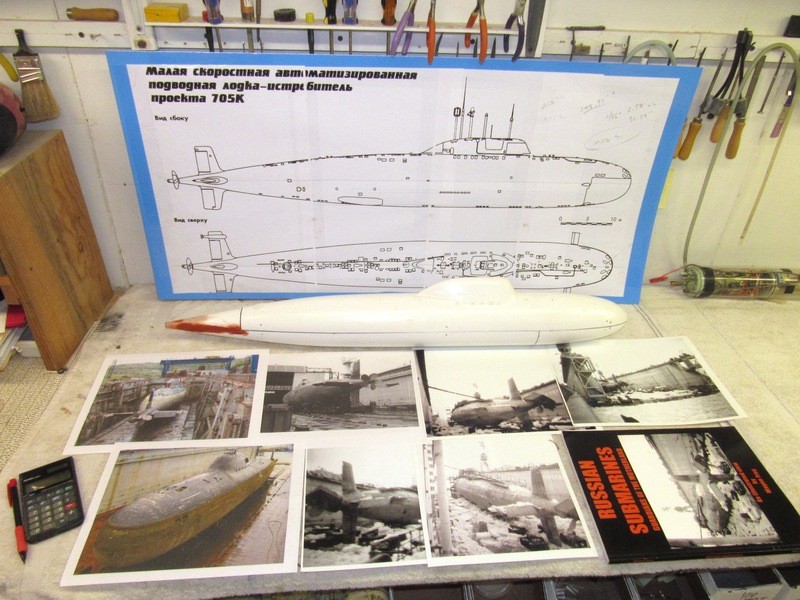
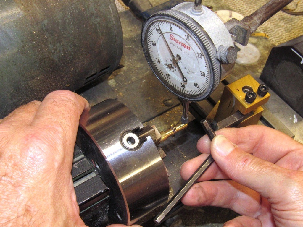
    All this work dedicated to the fabrication of masters, tools, and parts needed to flesh out the 1/96 Scale Shipyard ALFA kit. Almost there!

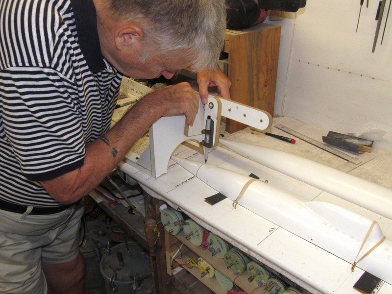
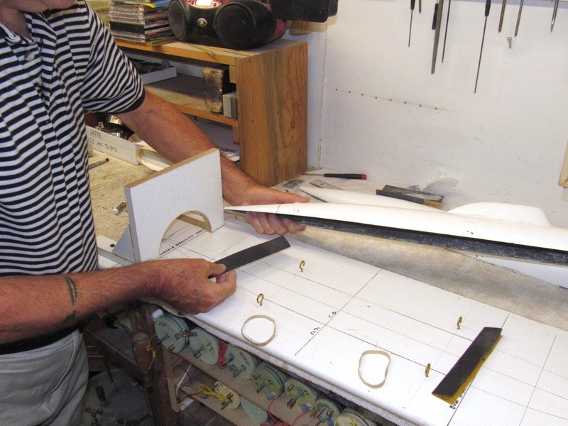
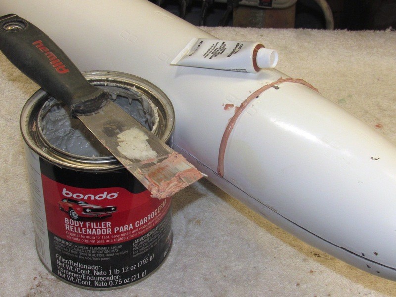
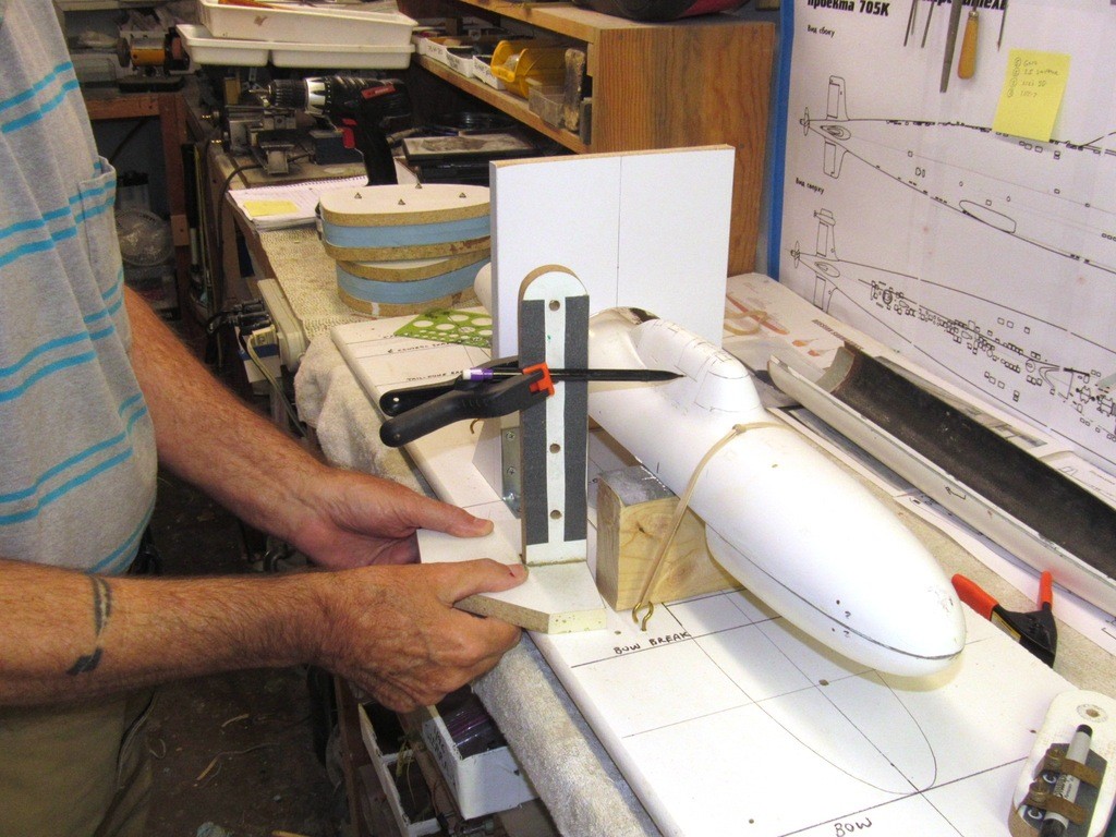
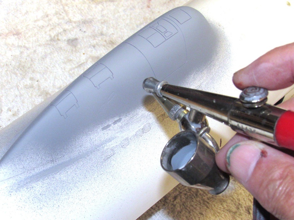
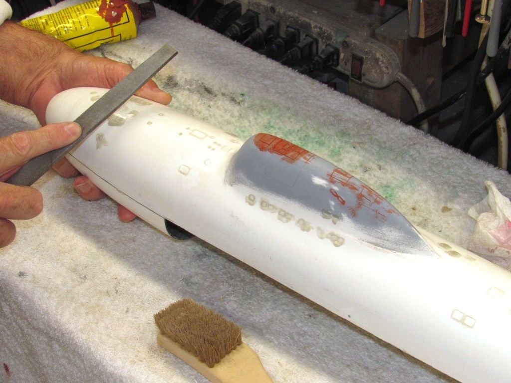
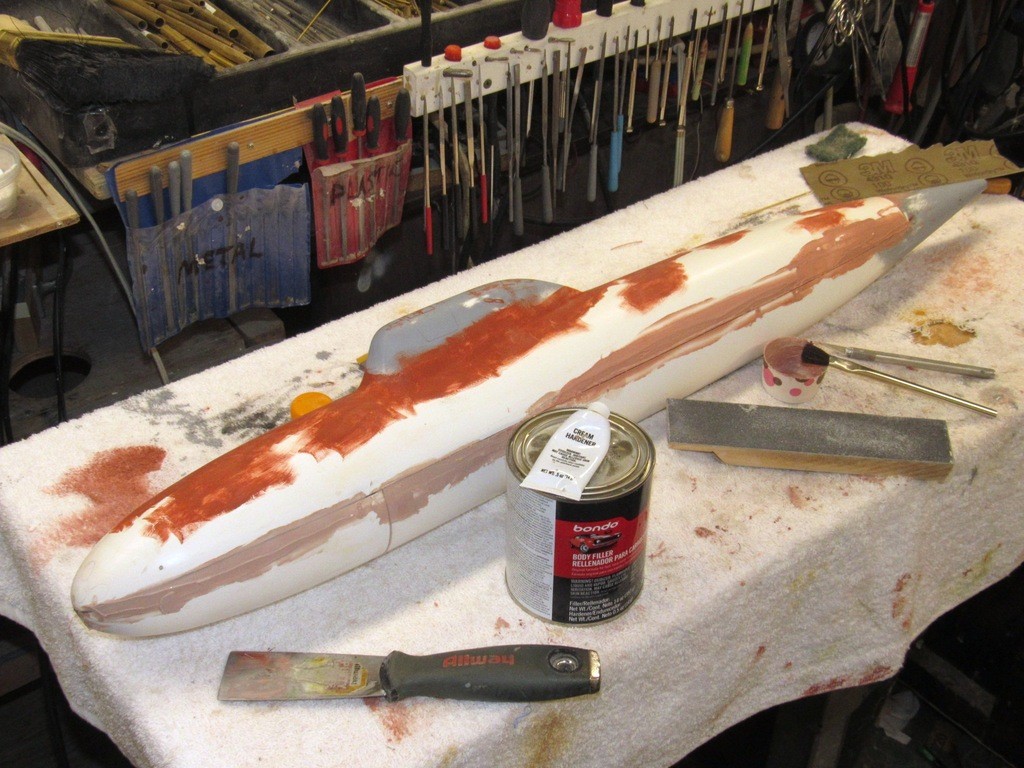
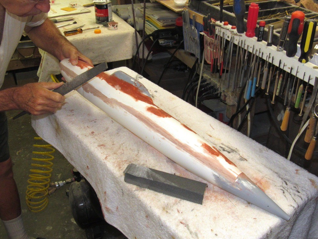
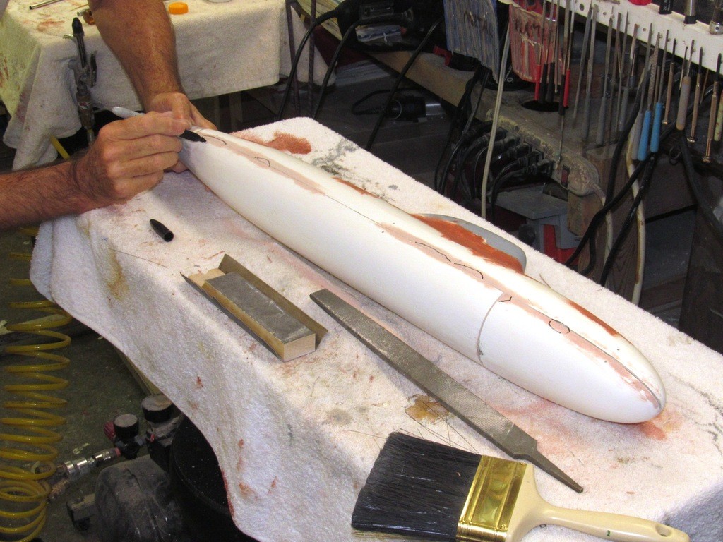
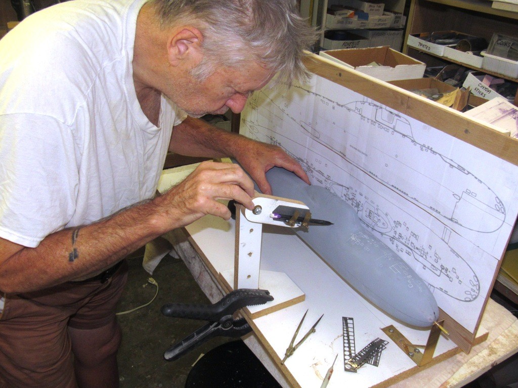
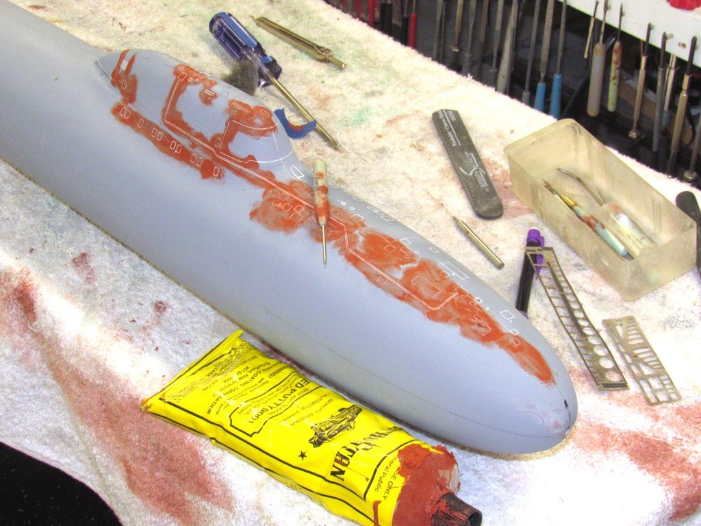
    Here I’m wet sanding the stern tapper of the hull. Best tool for simple curves like this is the sanding block or, as seen here, a length of stiff brass strip with sandpaper glued to its face. But, most of the work pictured here was the filling of file-marks, dings, and gaps found on the appendage masters with Nitro-Stan air-dry touch-up putty. The flaws revealed after spraying on the initial coat of gray primer.

    upgrading the SSY 1/96 ALFA kit VyKO8q

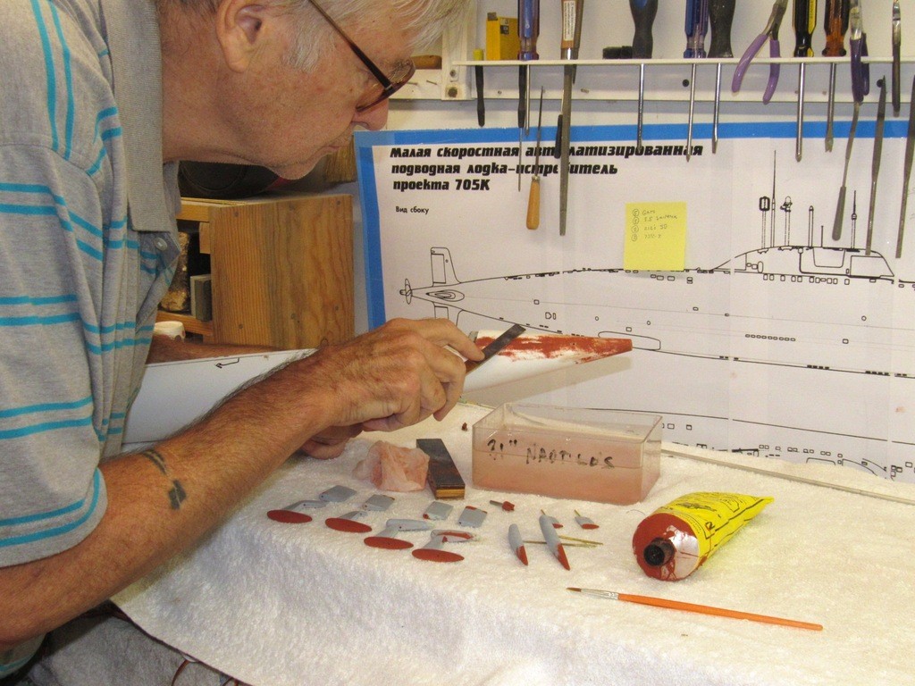
    The hardened putty was abraded down with various sanding tools ranging in grits from #400 to #600, the #600 grit producing scratches small enough to be easily filled by a moderate coat of primer. All sanding at this stage is done wet: the work is either dunked in water or water applied with a wet paper towel, and the sanding tool dunked in water periodically to keep the cutting surface clear of abraded particles.

    Abrasion: the process and tools is such an important and varied topic that I’ve gone out of my way in this installment to give the subject special attention. Abrasion is so much more than scrubbing a models surface with a loose piece of handy sandpaper and calling it a day!

    upgrading the SSY 1/96 ALFA kit Tr7gu9

    I pride myself on exacting adherence to shape, symmetry, and smoothness of finish, be the work a master or the display piece itself. This achieved by the proper use of tools. Tools designed for specific jobs; coupled with the wisdom, (acquisition of information and practice of process) to chose the correct tool for the specific job at hand, and the ability to create tools when none are at hand. Understanding the many types and grades of grit; physical characteristics of the grit backing; ability to form the abrasive to cut as directed; and to have developed the motor-skills needed to work these tools with exactness is a prerequisite.

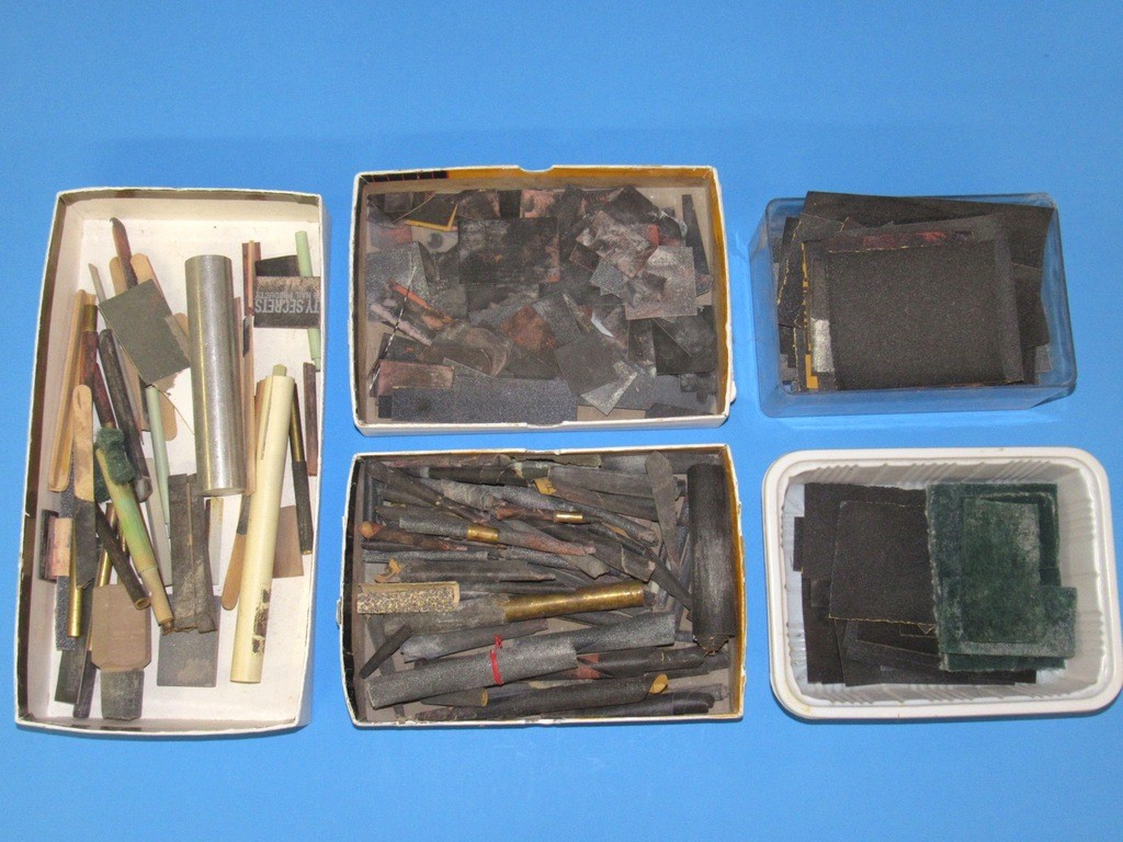
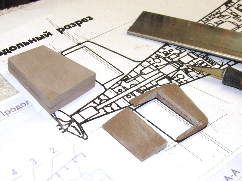
    Below is some of the specialized abrasion tools formed from sandpaper. Various small, stiff sanding blocks of flat, simple, and compound curved shape; stiff double-sided sanding pieces; twisted sanding tools for radius cutting; and end-cuts of raw sandpaper of various grit grades ready to be turned into a specific tool.

    upgrading the SSY 1/96 ALFA kit MtWHcJ

    In the old days the only commercially available sanding sticks were the ones sold as nail-files, and most of those of unknown grit and quality.

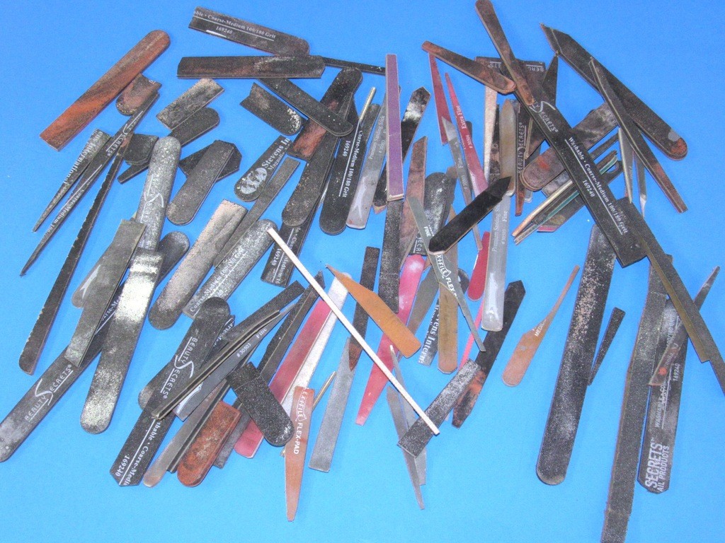
    Today, there is a wide range of commercially available sanding sticks featuring pliable backings. These sanding sticks have as their core a material that ranges from reasonably stiff to spongy soft. They feature materials that are water resistant and are stout enough to give long service, wet or dry. These sanding sticks can be re-surfaced with another layer of grit if the need arises.

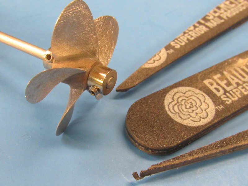
    A tip: If you can find a bag full of sanding sticks of the grit and size you need from the down-town beauty-supply house, then get them in bulk from that source as the local hobby shop will charge you two-bucks for a single stick of the same thing -- why pay more if you don’t have to?

    (Today’s franchise hobby-shops are only good for bad advice, magazines, r/c toys, and glue. Other than that look elsewhere for your model-building needs).

    upgrading the SSY 1/96 ALFA kit 09Dsuh

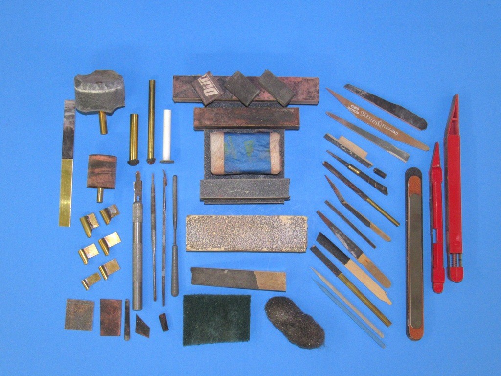
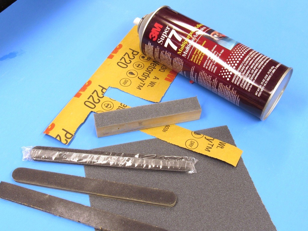
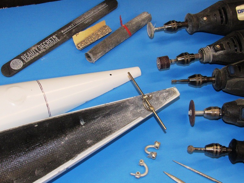
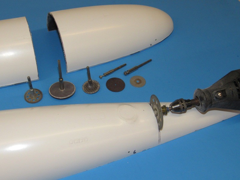
    More examples of abrasives mounted in unconventional ways. Metal backed sanding blocks, soft backed sanding blocks, tubular backed sanding blocks; convex sanding sticks; rotary sanding drums; chisels (just snuck that in to see if you were paying attention); riffler and specialized jeweler’s files; steel-wool, 3M abrasive pad; twisted sandpaper; pointed abrasive coated dowels of various grits (useless!!); and specialized continuous-belt sanding sticks.

    All are means of grinding away the surface of the work at hand. The trick is knowing the surface physical characteristics of the work and what abrasive tool is suitable for the job.

    upgrading the SSY 1/96 ALFA kit 6KcBDn

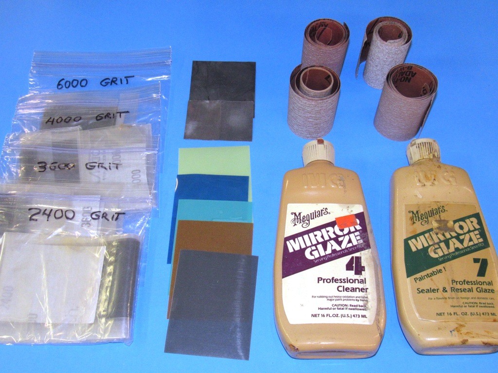
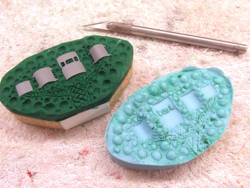
    Polishing is abrasion, but with a much finer grit. That grit bonded to a backing like the more common varieties of sandpaper of cloth, foam, or Mylar. Or, the fine grit is suspended in a liquid vehicle such as oil or water and is applied and worked over the subject being polished with a cloth, wet stick, or polishing wheel. These specialized abrasives find little utility in the world of model ships and submarines other than rendering transparent items, bridge window, deadlights, navigation light lenses, and searchlight lenses optically transparent.

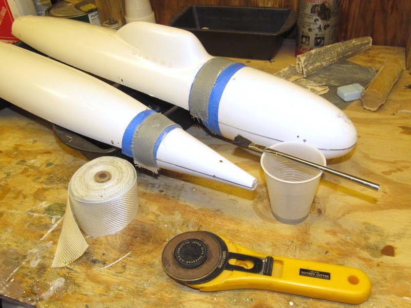
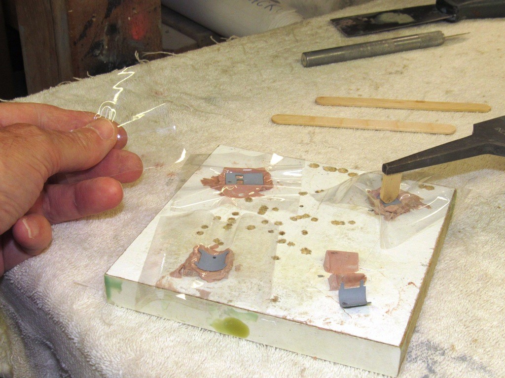
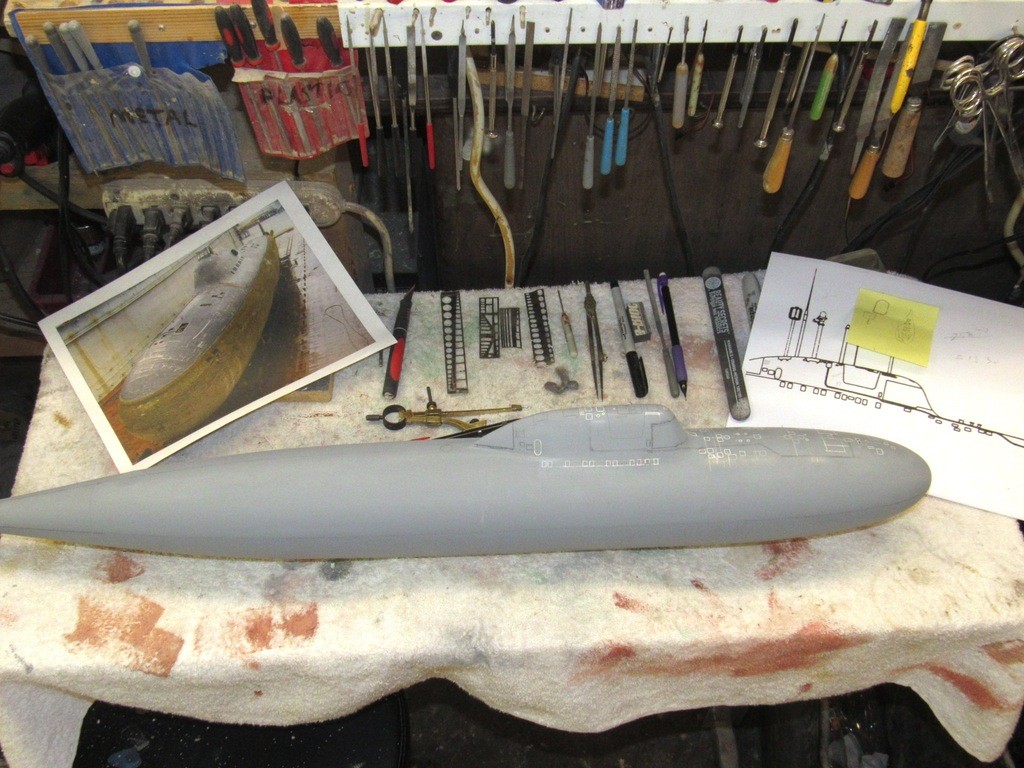
    Brian Starkes, who is a Master at this game, gave me a steer to a line of contact-adhesive backed rolls of sandpaper of various grits – those four rolls you see in the upper right of the picture below. This is a neat product and permits you to quickly mount it to a stick or dowel in seconds. Brian owns and operates a big-time automotive refinishing shop and he’s taught me a lot about abrasive use and sources of supply over the years. And his model work has to be seen to be believed!

    https://forum.rc-sub.com/forum/builder-threads/133616-1-72-sturgeon

    upgrading the SSY 1/96 ALFA kit W42cAE

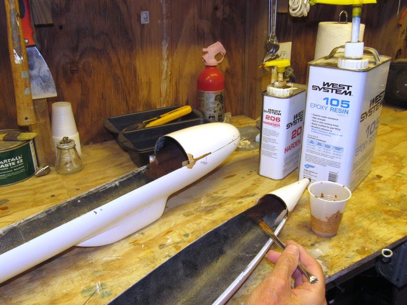
    A sanding block can be a simple stick of square wood with some loose sandpaper wrapped around it, or it can be a commercial tool usually made from extruded T-section aluminum. I prefer to take a length of Pine block and glue the sandpaper to one or more faces with the aid of contact cement. Being the impatient sort I accelerate the drying of the spray applied contact-cement with a heat-gun.

    When a foam-backed sanding stick gets worn down, I’ll apply contact cement to the worn face and slap on a fresh piece of sandpaper. Never throw out a sanding stick – you can always breathe new life into it.

    upgrading the SSY 1/96 ALFA kit D0fn8p

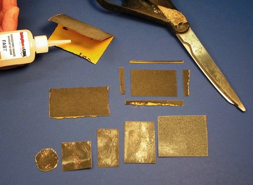
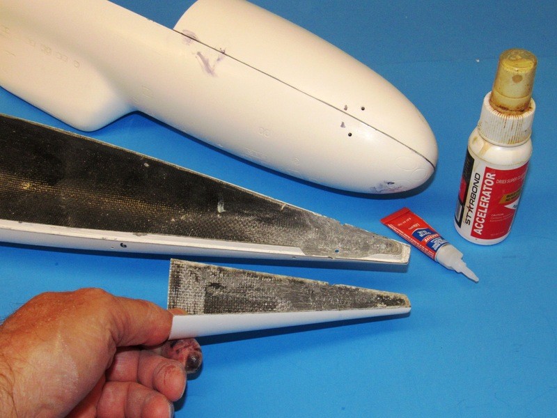
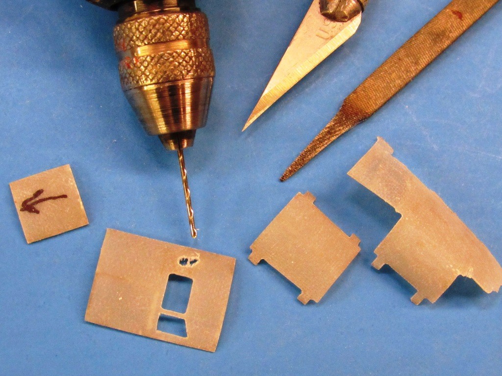
    Today’s sanding sticks, owing to their pliable cores, have enough give to make sanding of compound (complex) curves an easy matter. However, where you need a stiff, thin-sectioned abrasive tool to get into tight places and cut corners or edges with precision, double-sided sanding strips are the way to go.

    A double-sided sanding strip is made by selecting the grit you need, folding the sandpaper in half (cloth and mylar backed grit can be used this way too, but is more difficult to glue and not nearly as stiff as glue saturated paper), hitting its backside with CA accelerator, applying CA to the other half, and quickly folding over and sandwiching the joined halves under a weight and flat surface till the glue cures hard.
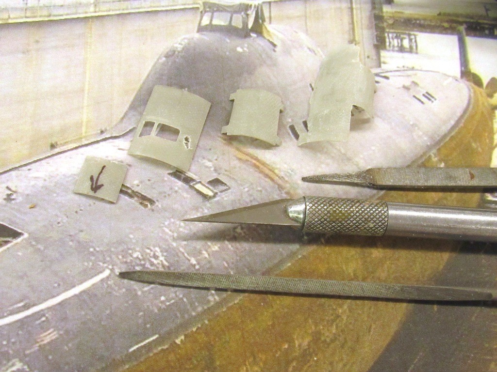
    The stiff sanding strip is cut with scissors to any shape that the job dictates.

    upgrading the SSY 1/96 ALFA kit PIFxDK

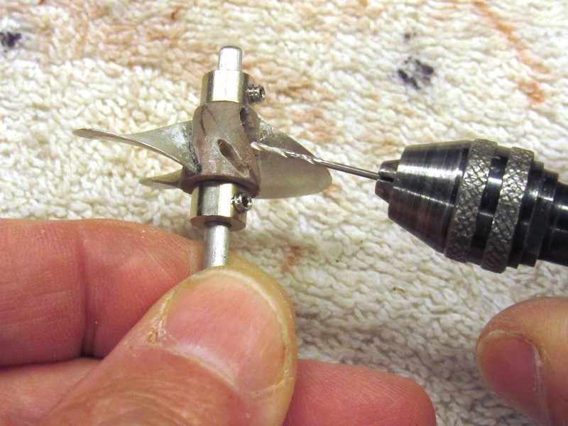
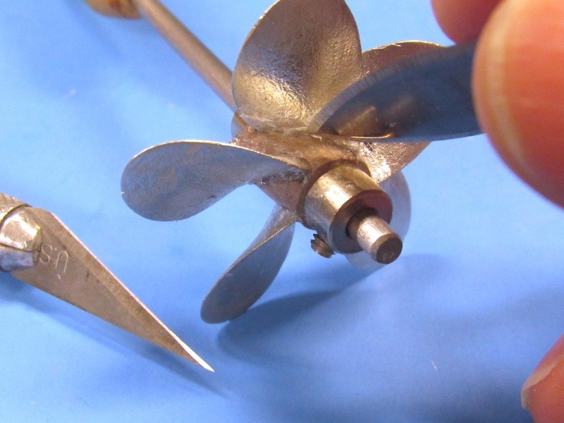
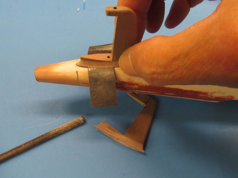
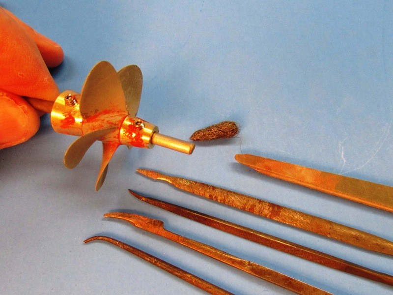
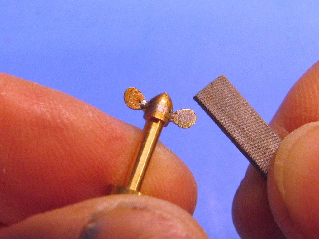
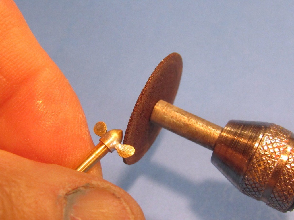
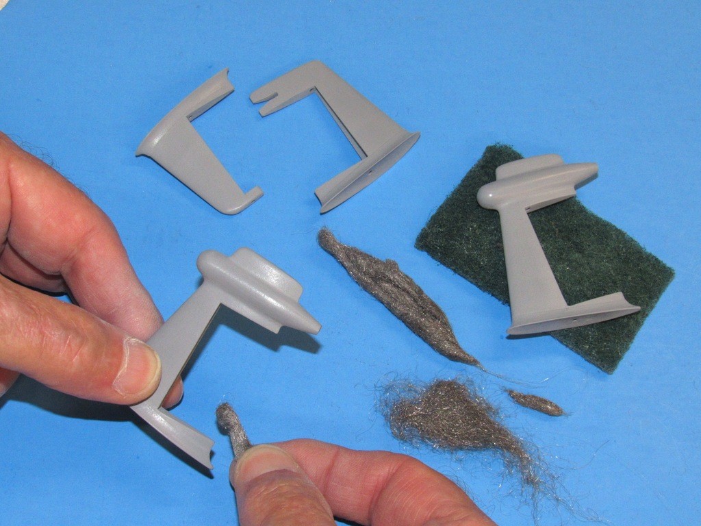
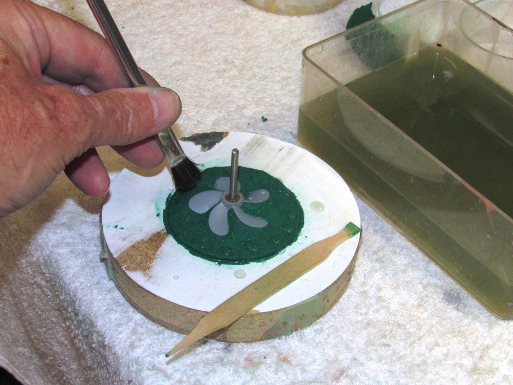
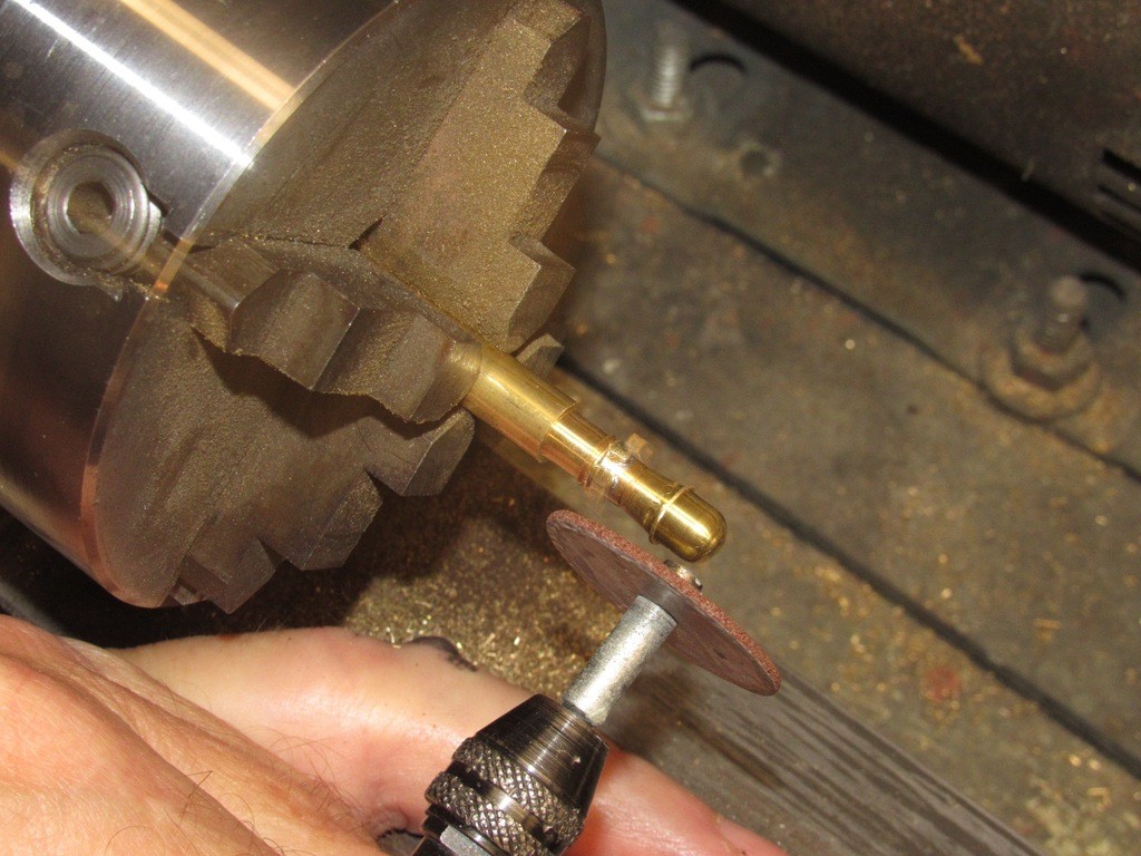
    As I demonstrated with the propeller blade-hub fillet work, there are occasions where you have to get around nearby structures to dig in where you need to abrade material away. Small files with exotically curved ends are sometimes the answer. And over the years these ‘riffler files’ have served me well in a variety of unique and otherwise impossible to do abrasion jobs.

    You can buy them commercially, but you are at the mercy of a pre-packaged file cut pattern, size and shape of curvature – often these store-bought rifflers just won’t do the job. So, to develop a tool best suited to a particular task, you take a common jeweler’s file of the desired cut and cross-section and give it a tip curve suited to the job at hand. You make your own riffler file. And when the job is done you add it to your ever growing collection of specialized abrasive tools.

    But, if you don’t want to be bothered forming your own, here’s a site where you can buy them: https://www.gesswein.com/c-131-rifflers.aspx

    upgrading the SSY 1/96 ALFA kit KyqhiK

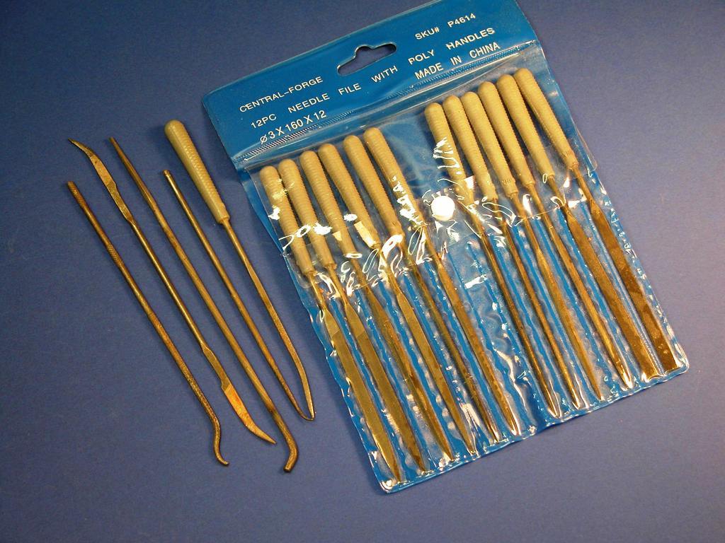
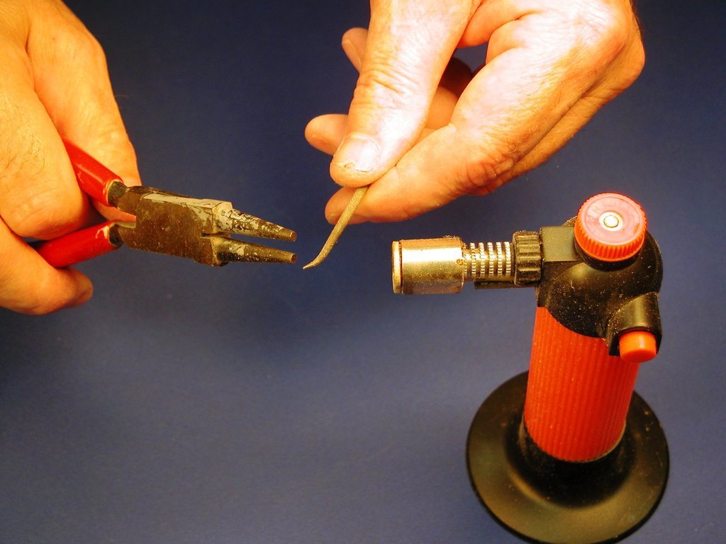
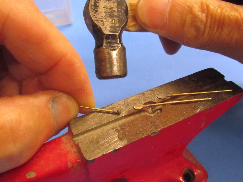
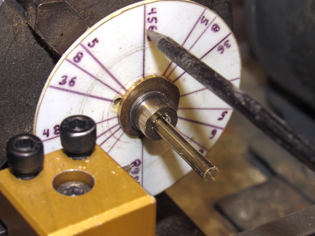
    It’s easy to bend high-carbon iron tools like this: Just get the work to a deep red heat and bend as required. Quench in water and you’re good to go.

    upgrading the SSY 1/96 ALFA kit ZN19sI

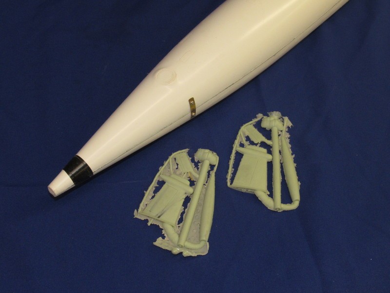
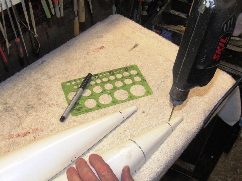
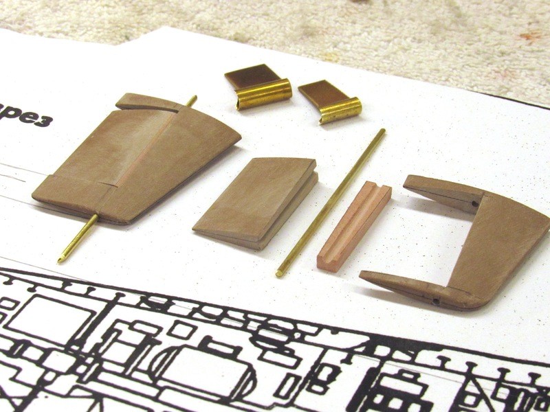
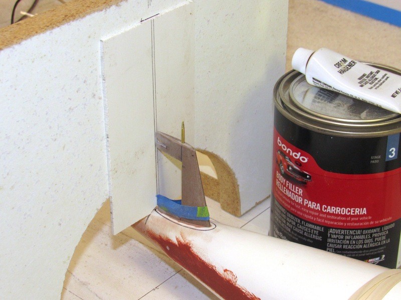
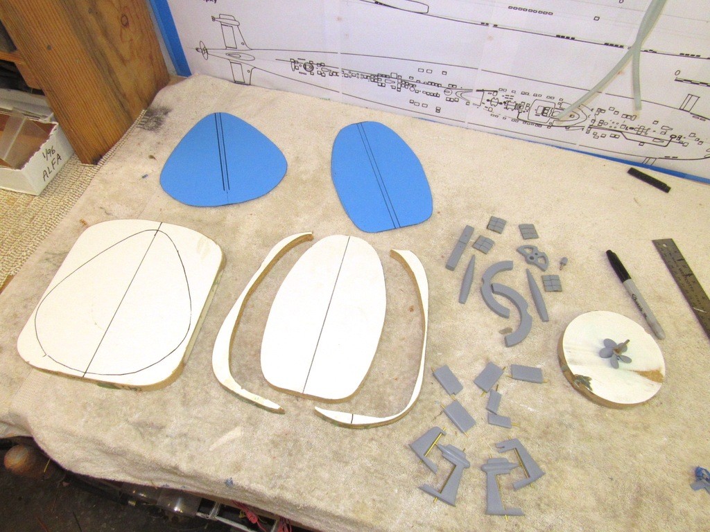
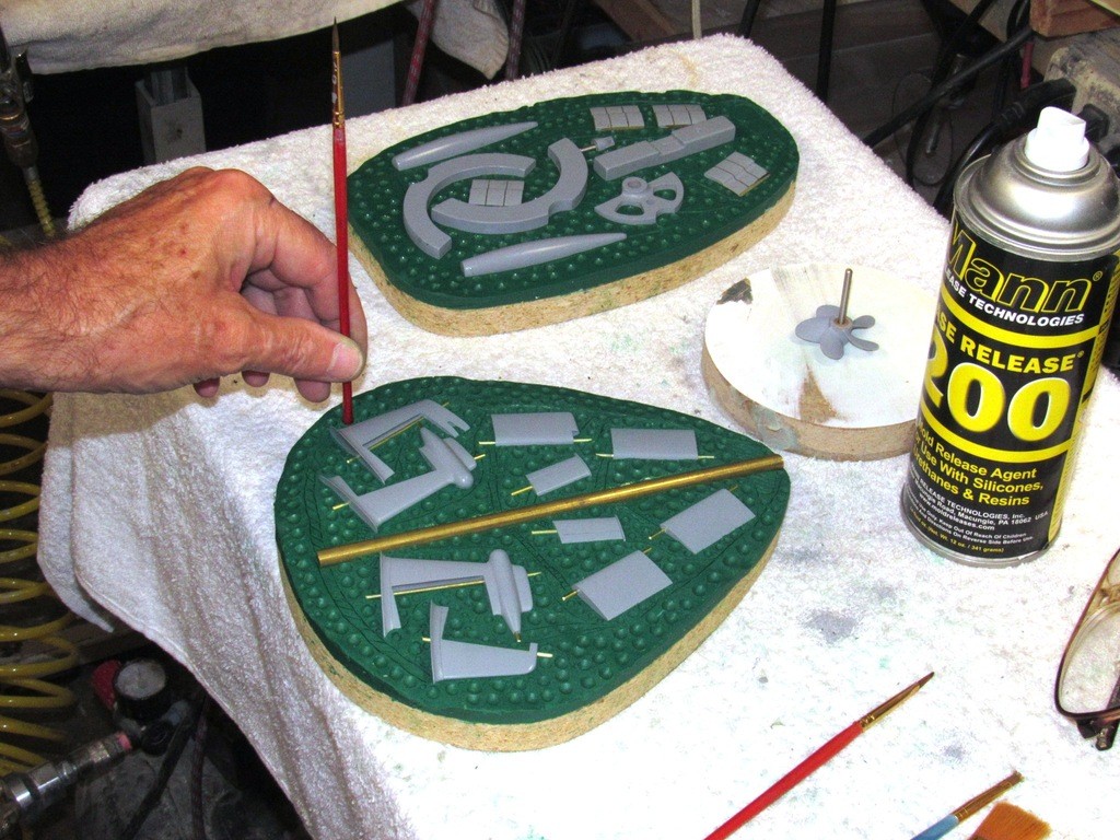
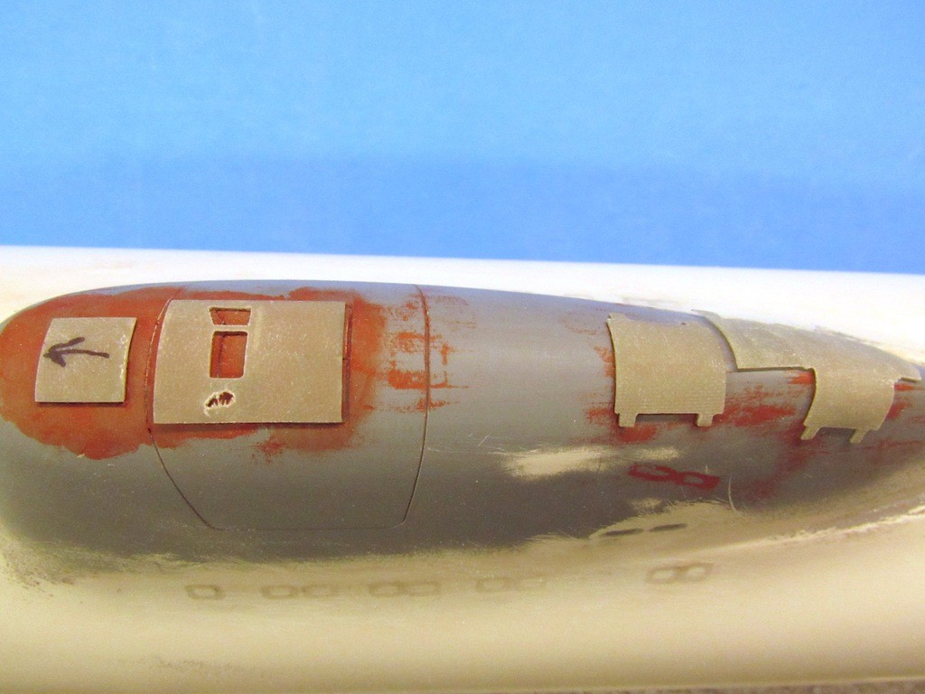
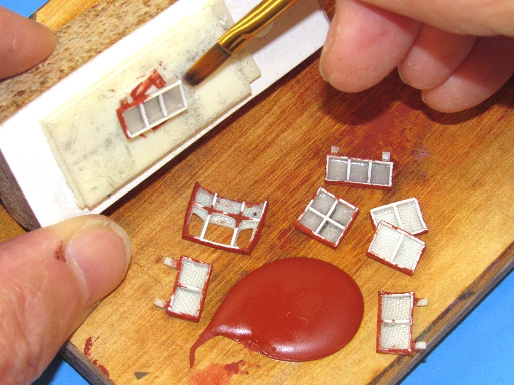
    Just about the last coat of primer to go down on the appendages.

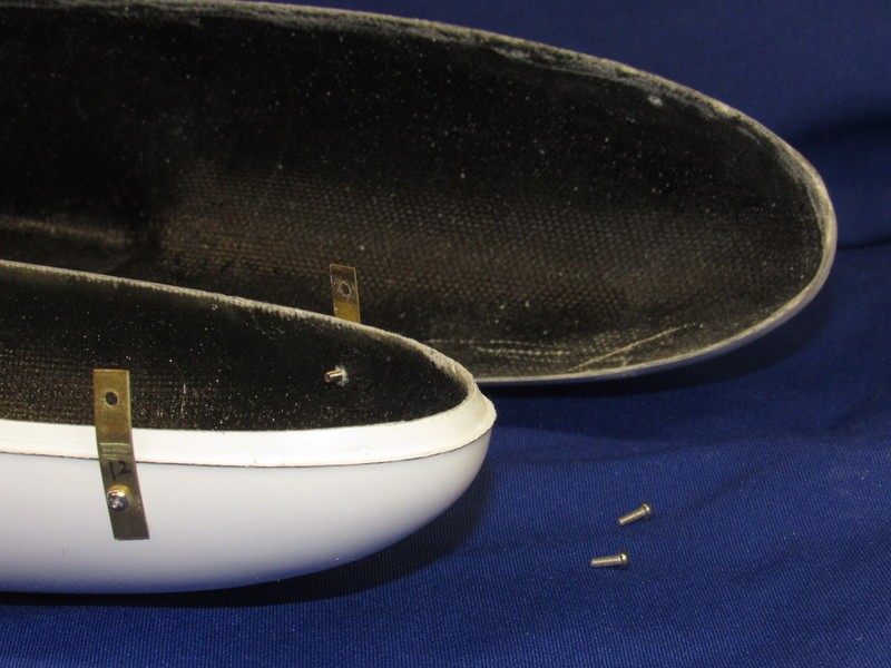
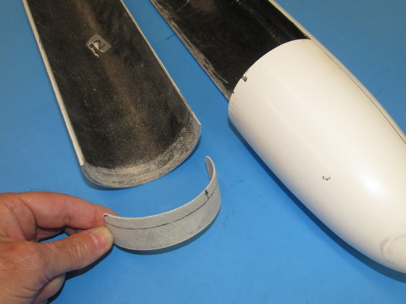
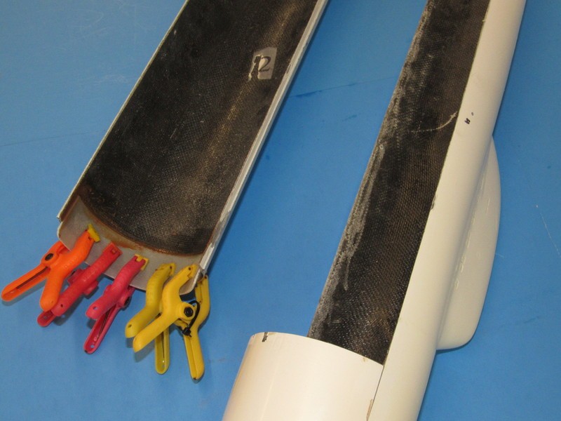
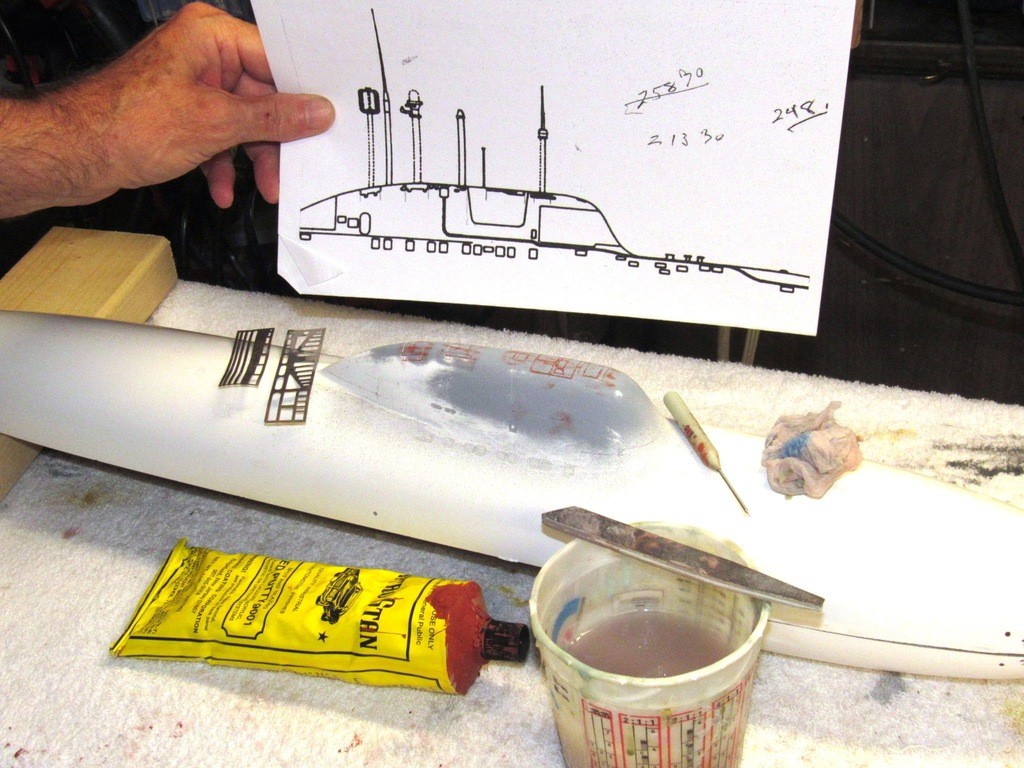
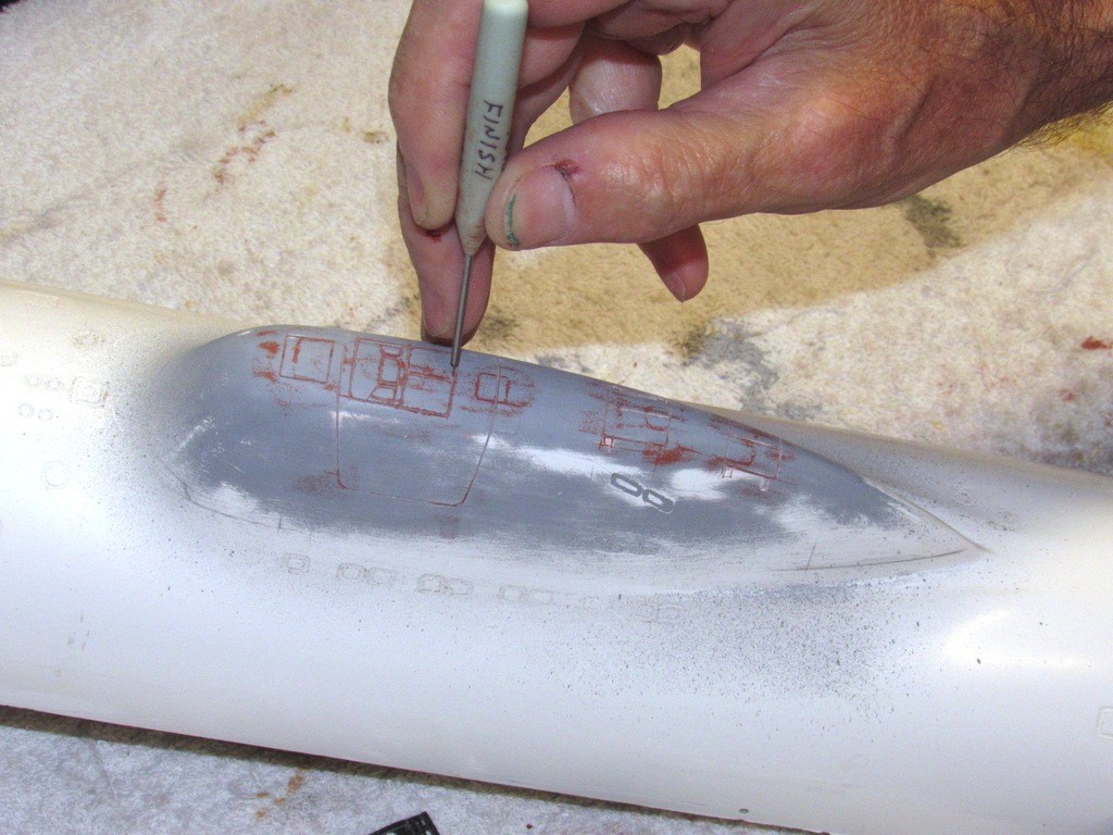
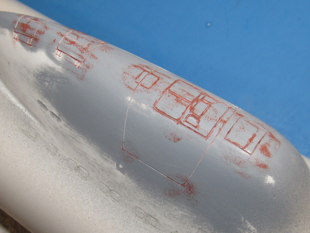
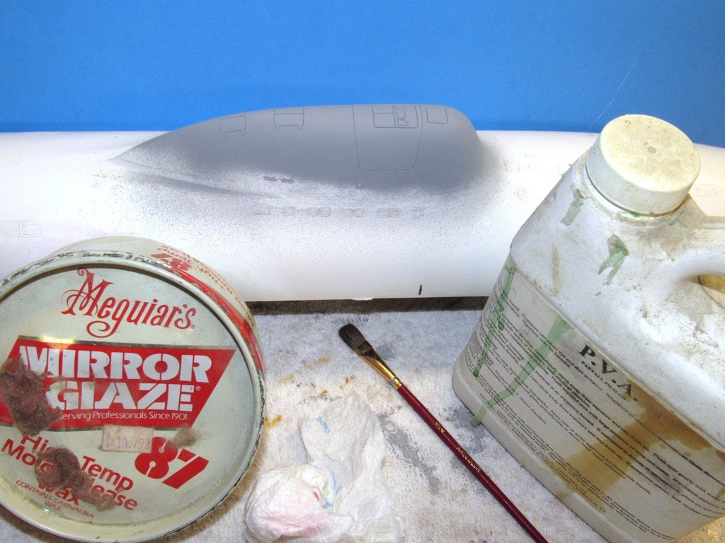
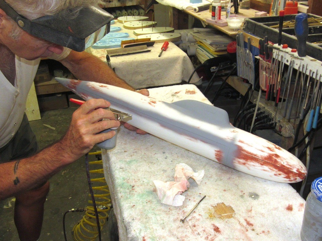
    This is the first shot of primer on the hull, and that localized to the stern where I did all the radial screeding, filler, putty, and sanding work. The rest of the hull is still in the raw. I’ve faired in the forward radial gap, but have yet to do the same to the after radial gap. Once those areas are tight I’ll install ‘capture lips’ to draw the longitudinal edges of the upper and lower hull tightly together – at which point another shot of primer will be laid down to find remaining problem areas.

    upgrading the SSY 1/96 ALFA kit SHKChx

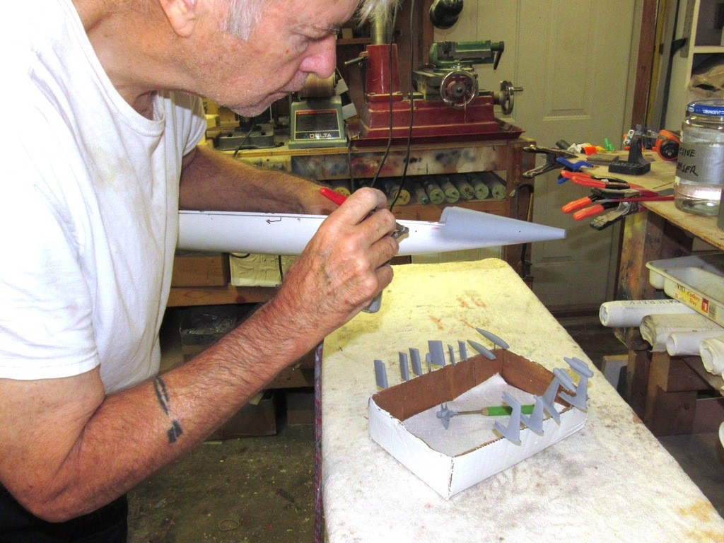
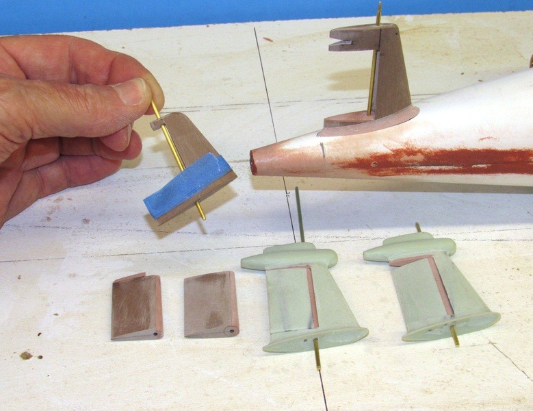
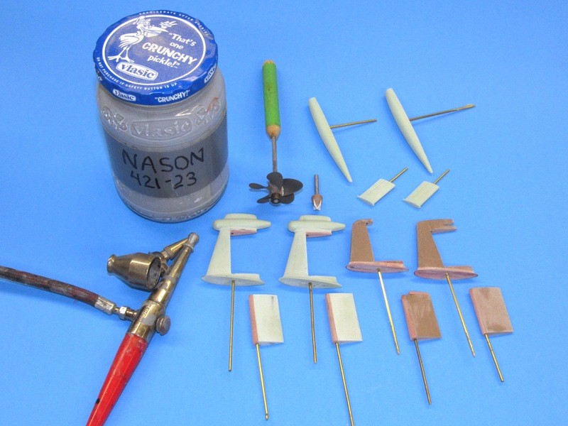
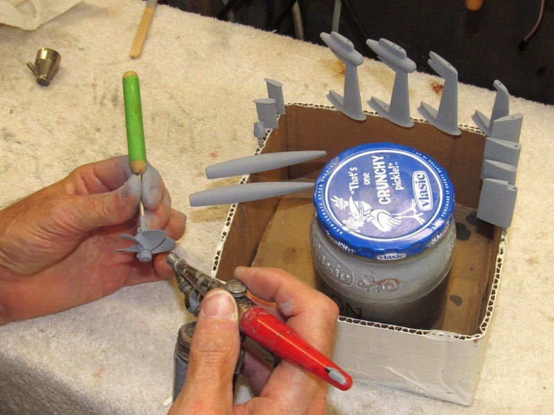
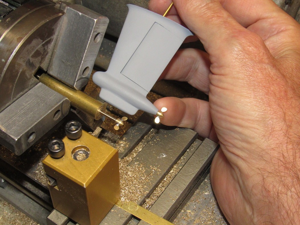
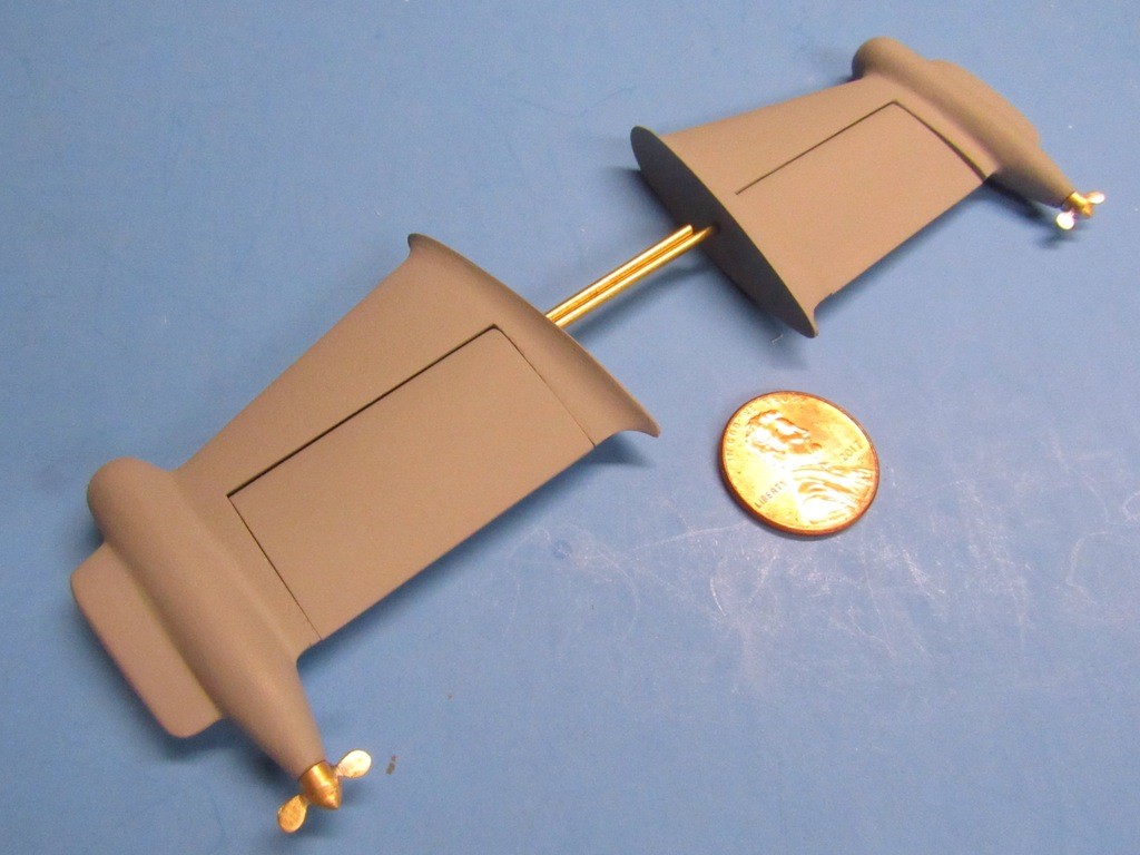
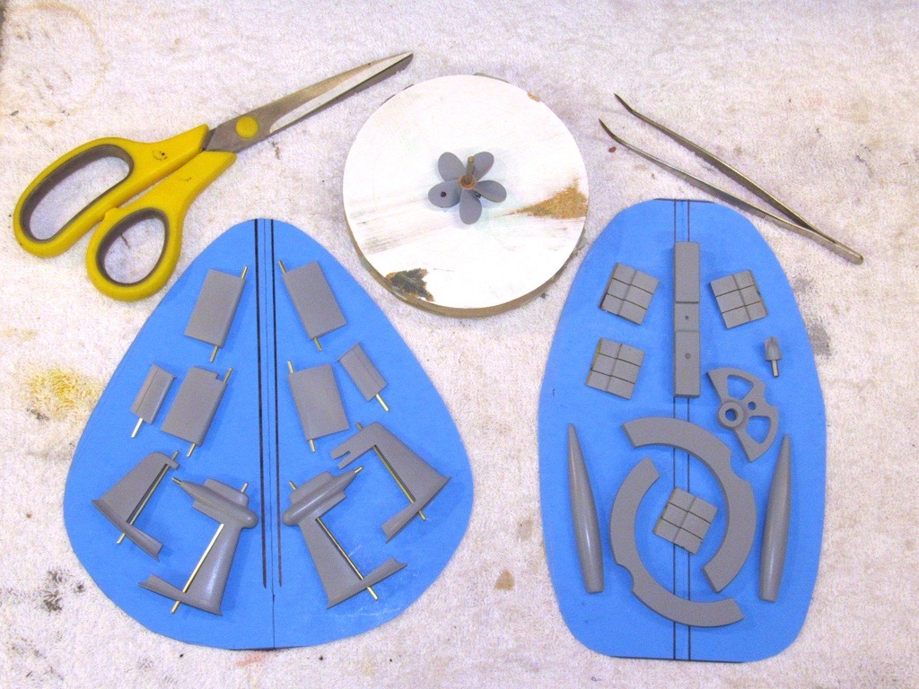
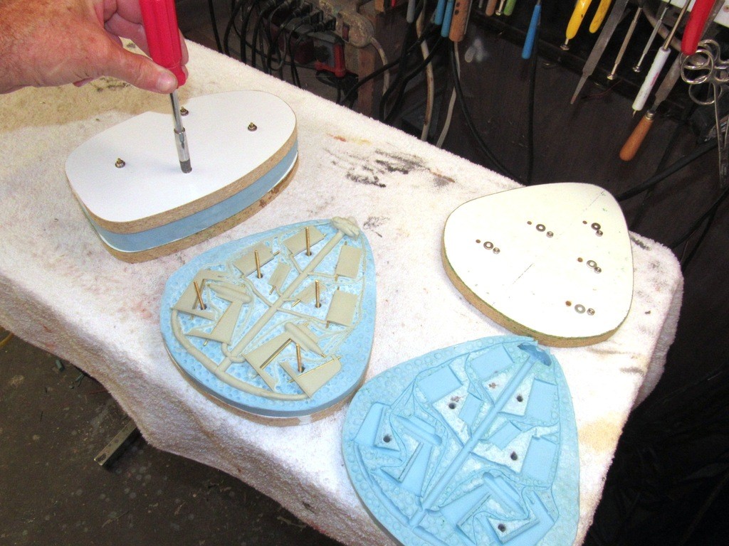
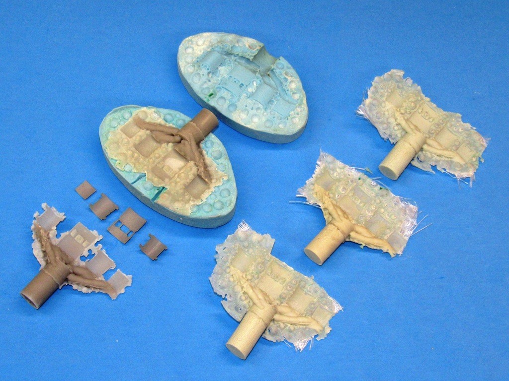
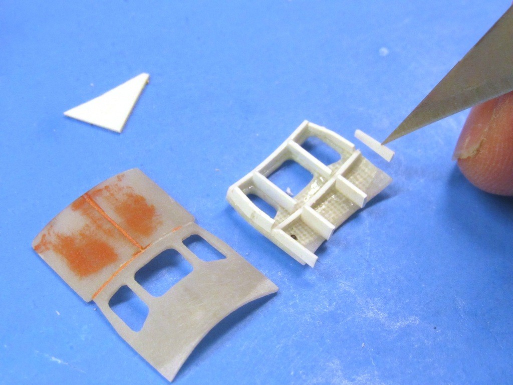
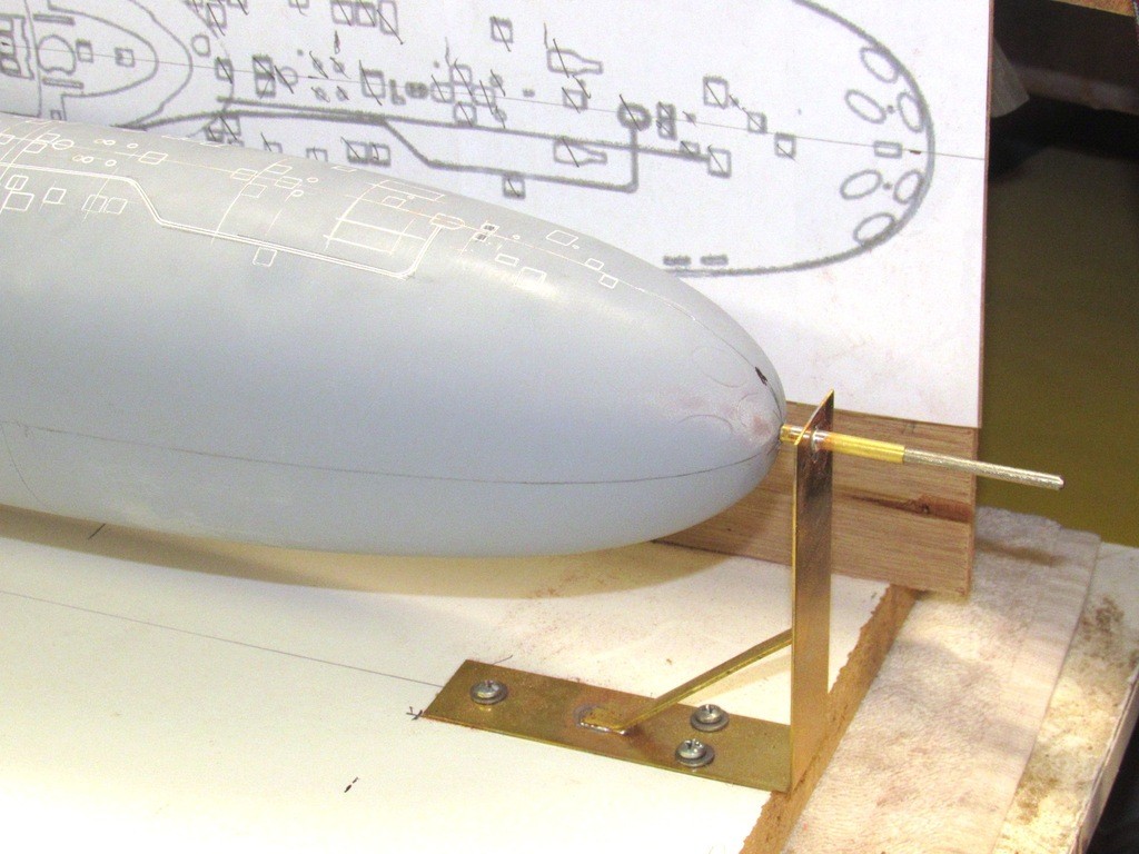
    Note that each master has been outfitted with a 1/16” brass rod holding fixture. These make it easy to handle these small items during priming and conveniently slip into the open honeycomb cells of a cardboard box, suspending the work as the primer dries.

    upgrading the SSY 1/96 ALFA kit 1NZ0WM

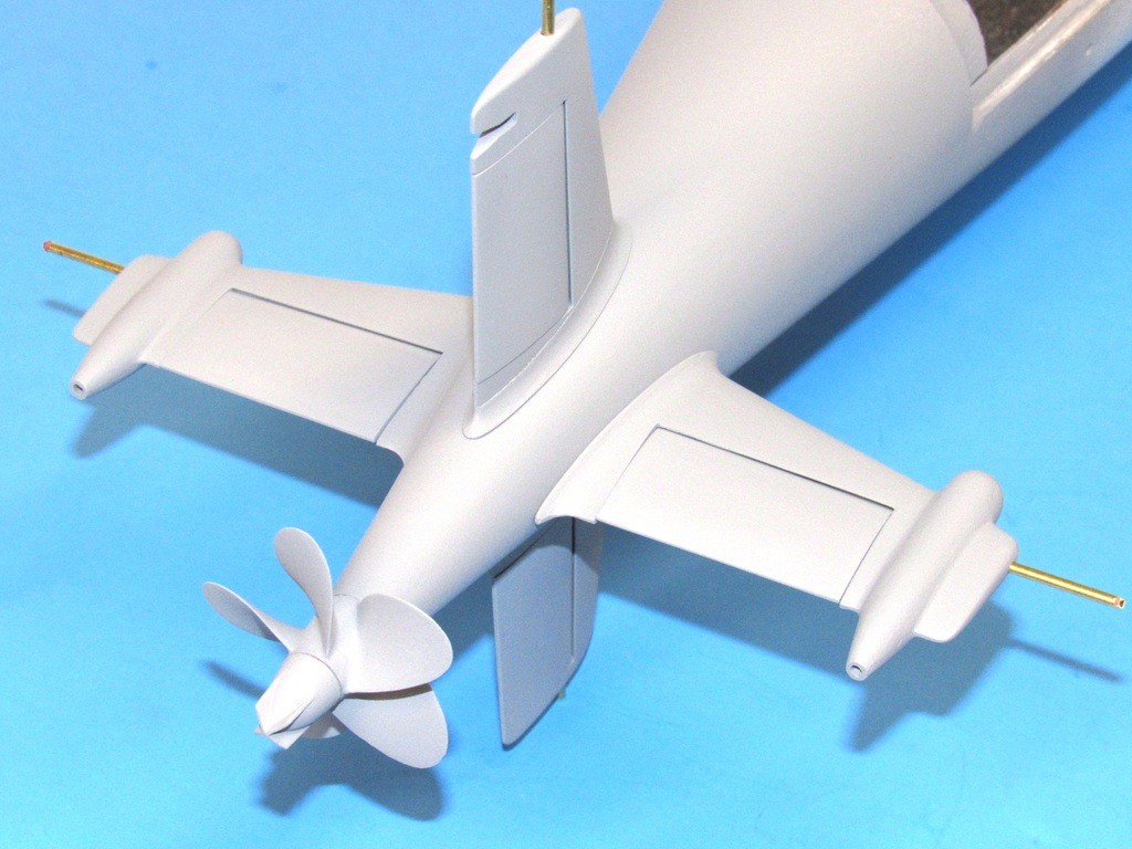
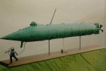
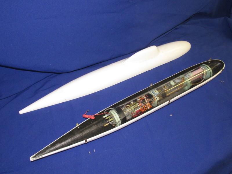
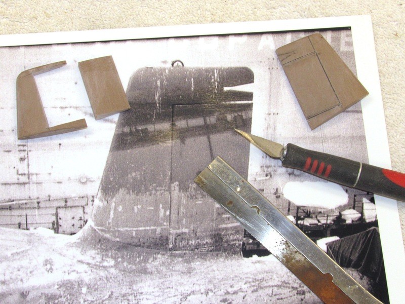
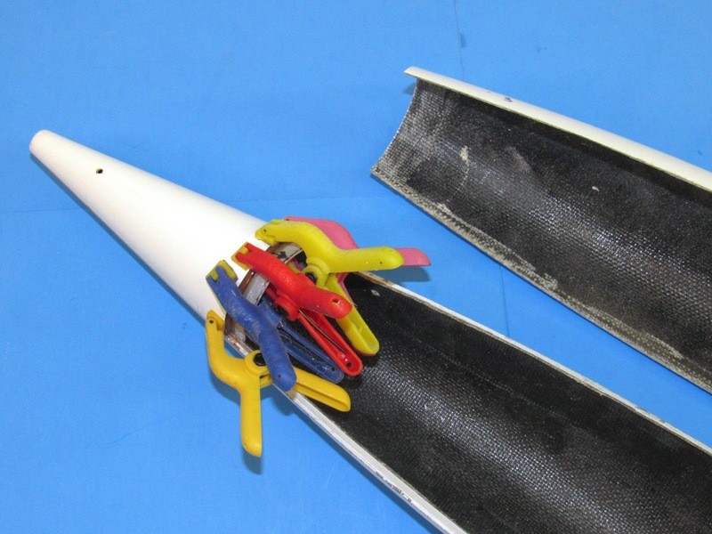
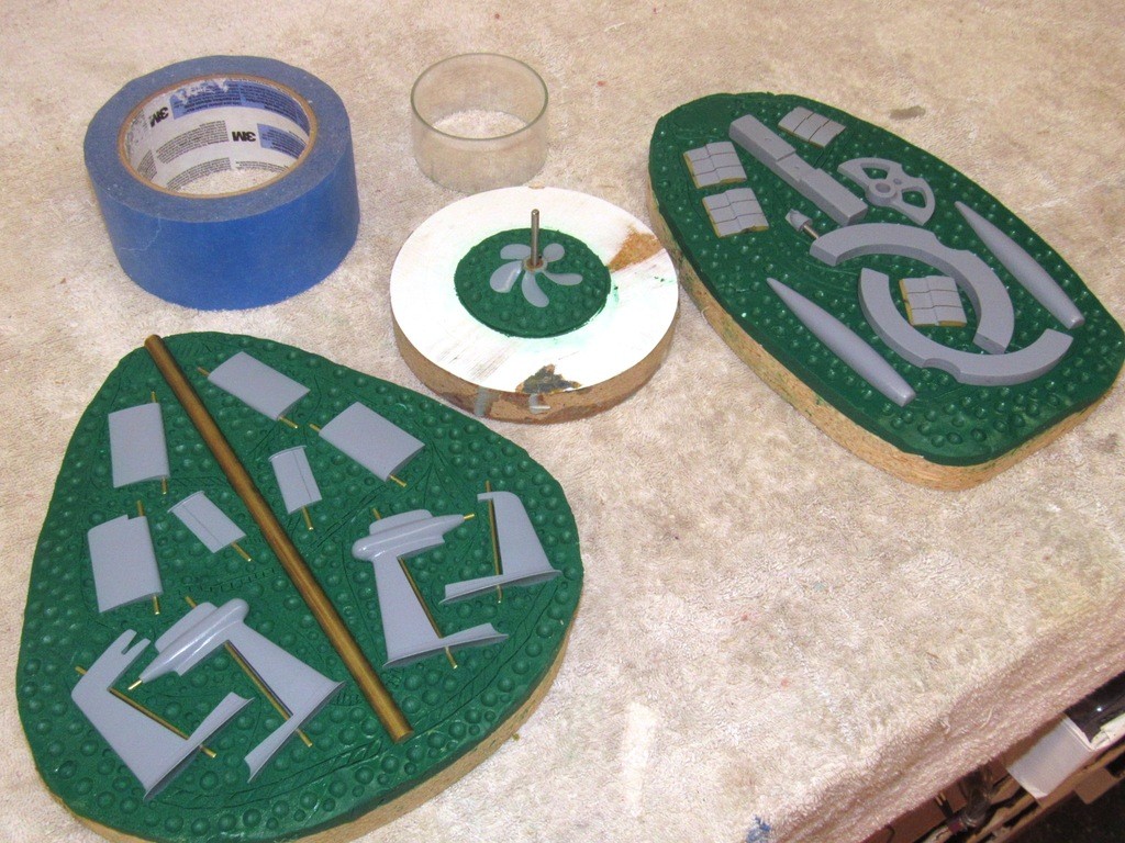
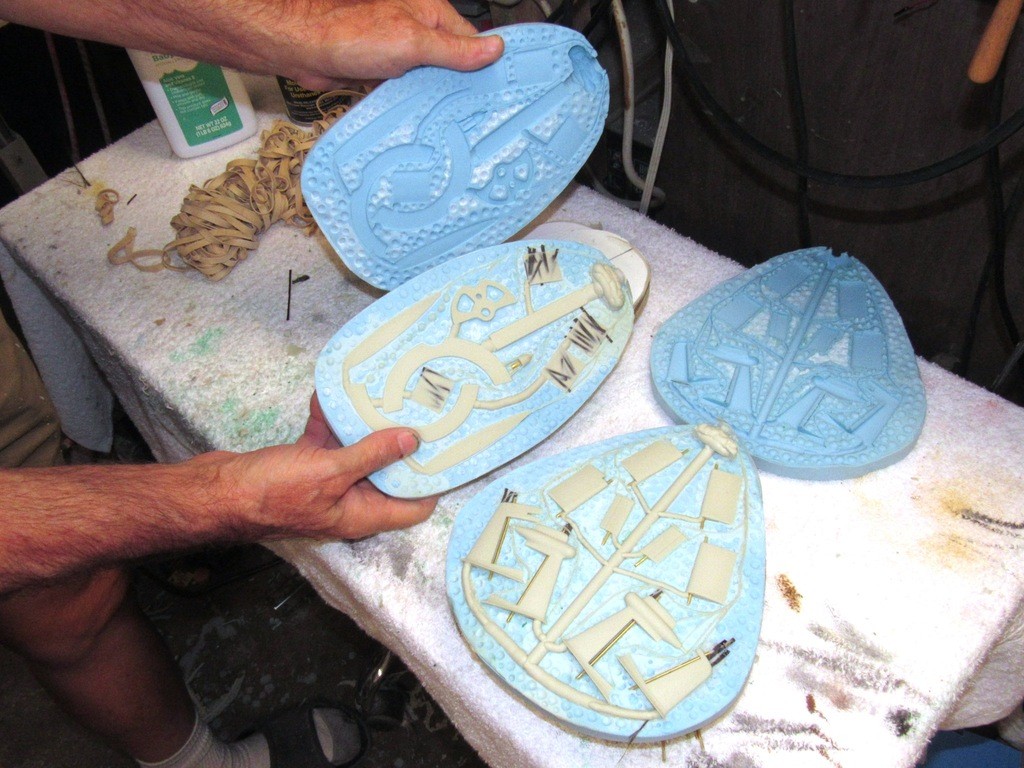
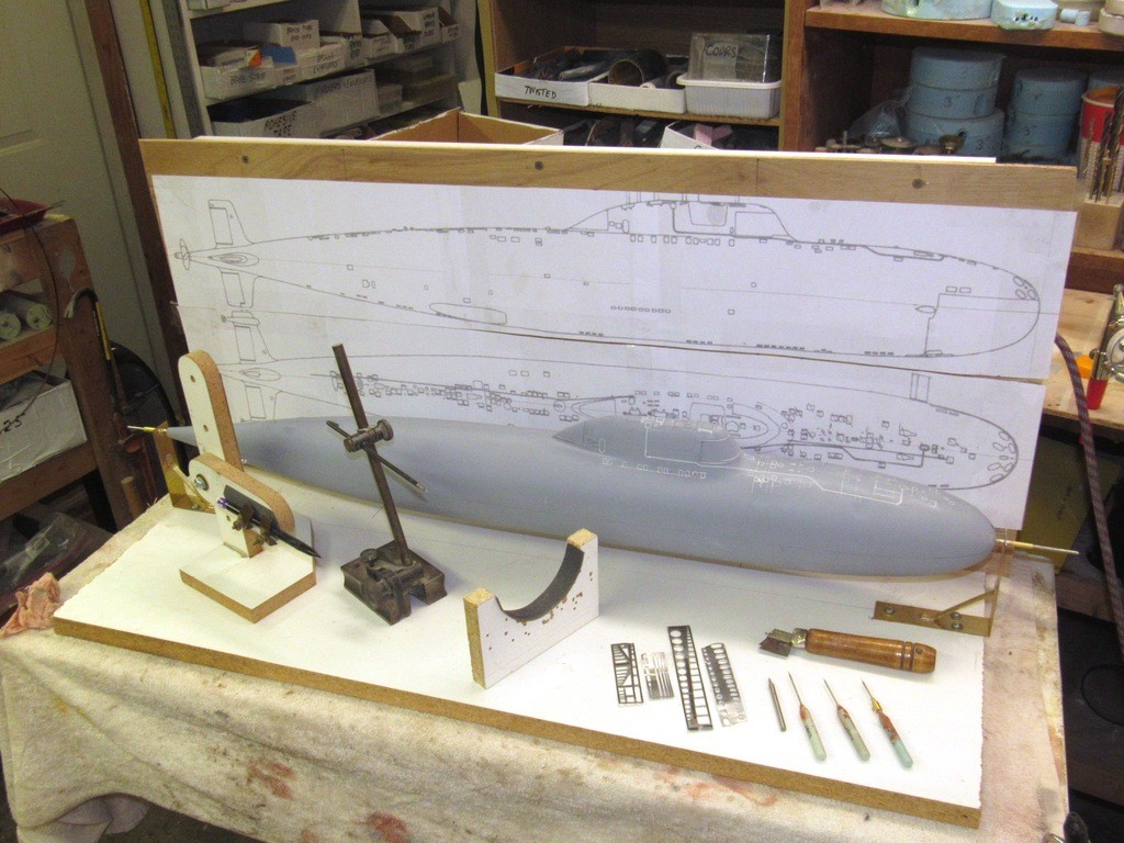
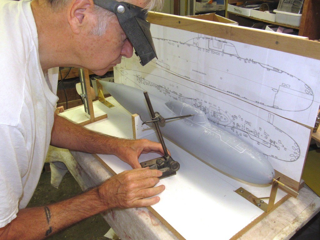
    I’m sure I’m not the only one who can’t wait, once parts are nearing completion, to test-fit things together just for fun … and to examine the mock-up for symmetry and ease of fit. “Yup, looks like the ass-end of an ALFA to me!”

    In foreground are the masters for the secondary loop condenser scoops and bow planes.

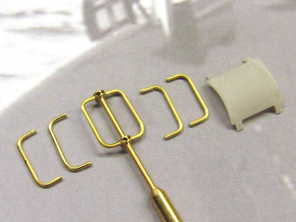
    (The ALFA bow plane linkage on the eventual r/c model presents a special problem as the port and starboard planes do not fall along the same horizontal plane – they are slightly off-set from one another in height. So, I can’t just run an operating shaft between the two. I’ll likely provide an internal bearing tube for each operating shaft and use a piece of flexible tubing between them to handle the off-set between the shafts. We’ll see. Plans change as the practical installation matures in my hands. More on this little problem later.)

    upgrading the SSY 1/96 ALFA kit YdHzrq

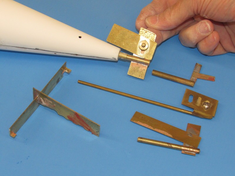
    Test fitting the horizontal and vertical stabilizers without aid of tape or glue was made possible by the control surface operating shafts. The horizontal stabilizers shared a single shaft that passed through the hull. As all four operating shafts are on the same vertical plane the vertical stabilizer shafts used here for the mock-up fit only extended less than half-way into the hull till they hit the horizontally running horizontal stabilizer shaft. The arrangement was a bit wobbly, but good enough for the pictures presented here.

    I’m almost ready to make tools from these appendages. Only chore remaining is to fill and sand some sanding scratches, and build up the slightly raised edge of the horizontal stabilizer fillets.

    upgrading the SSY 1/96 ALFA kit AAJ08Z

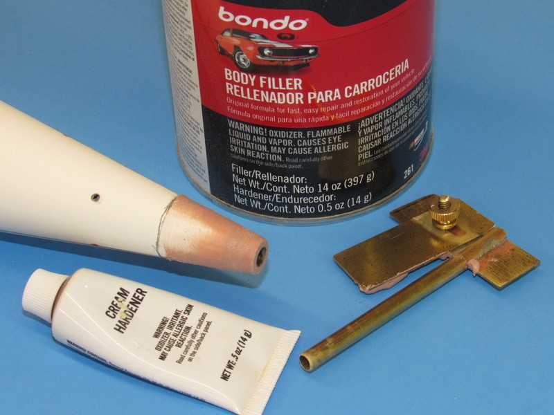
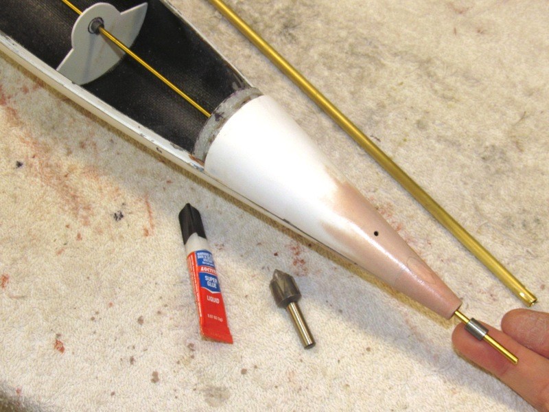
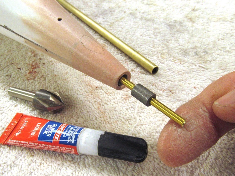
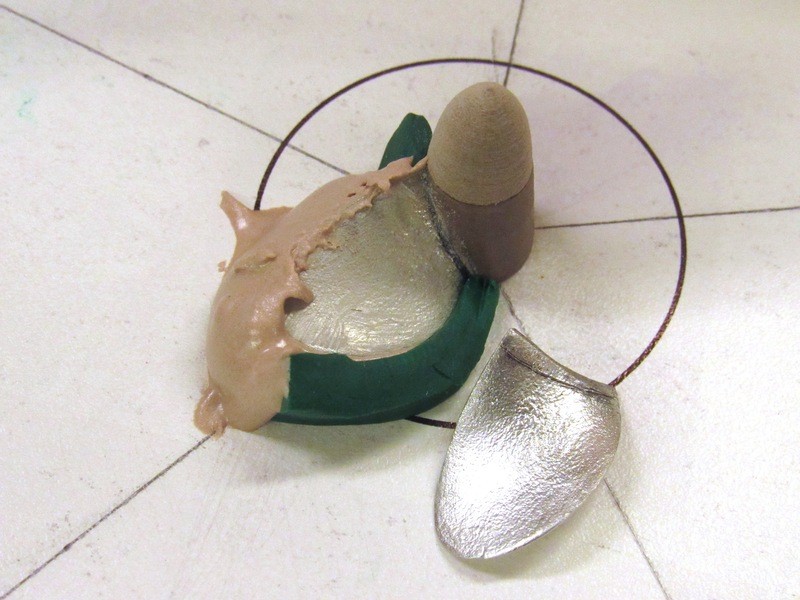
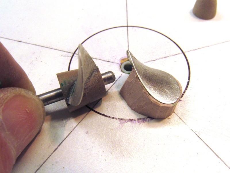
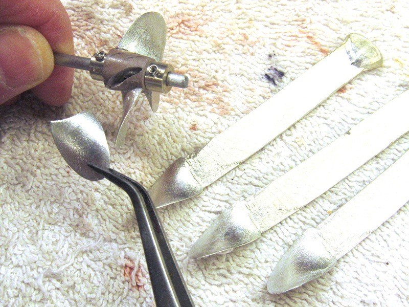
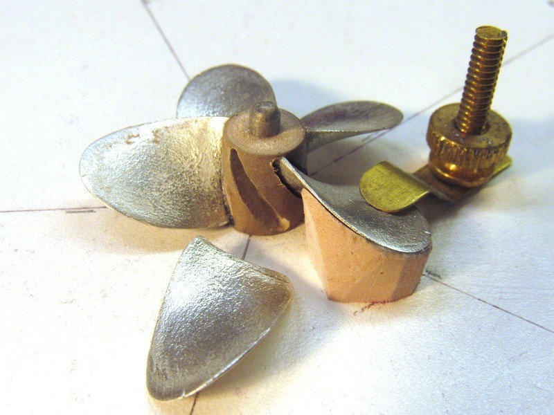
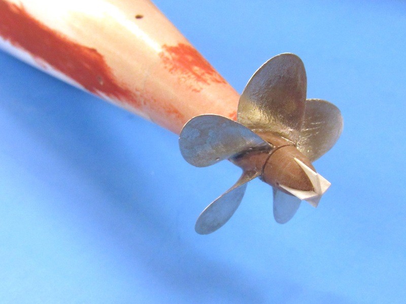
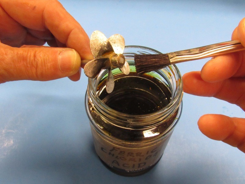
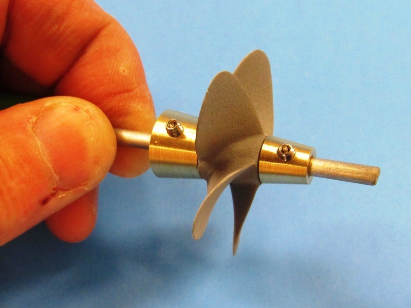
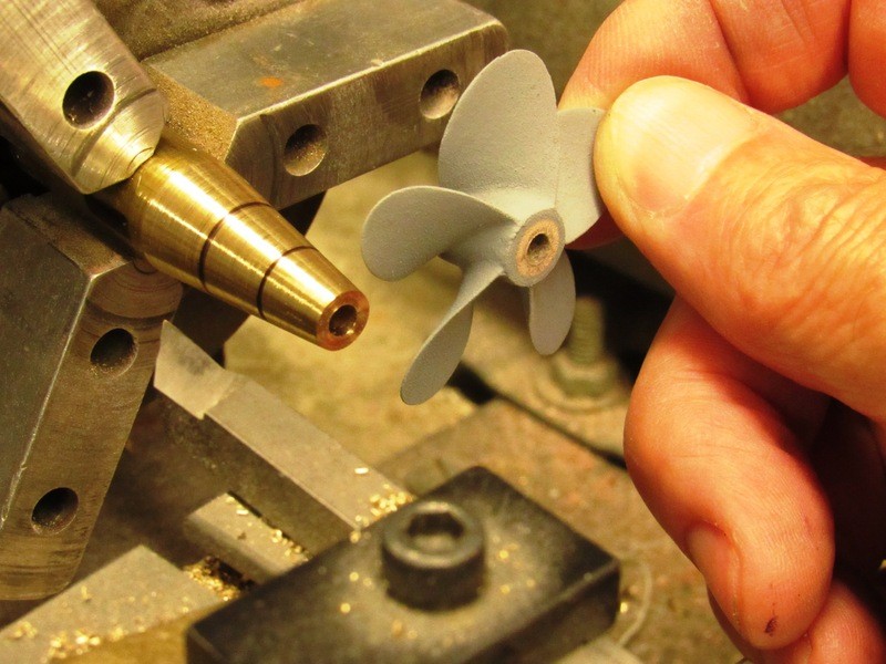
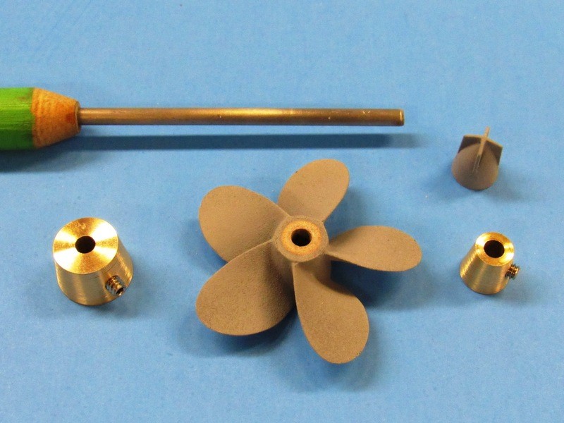
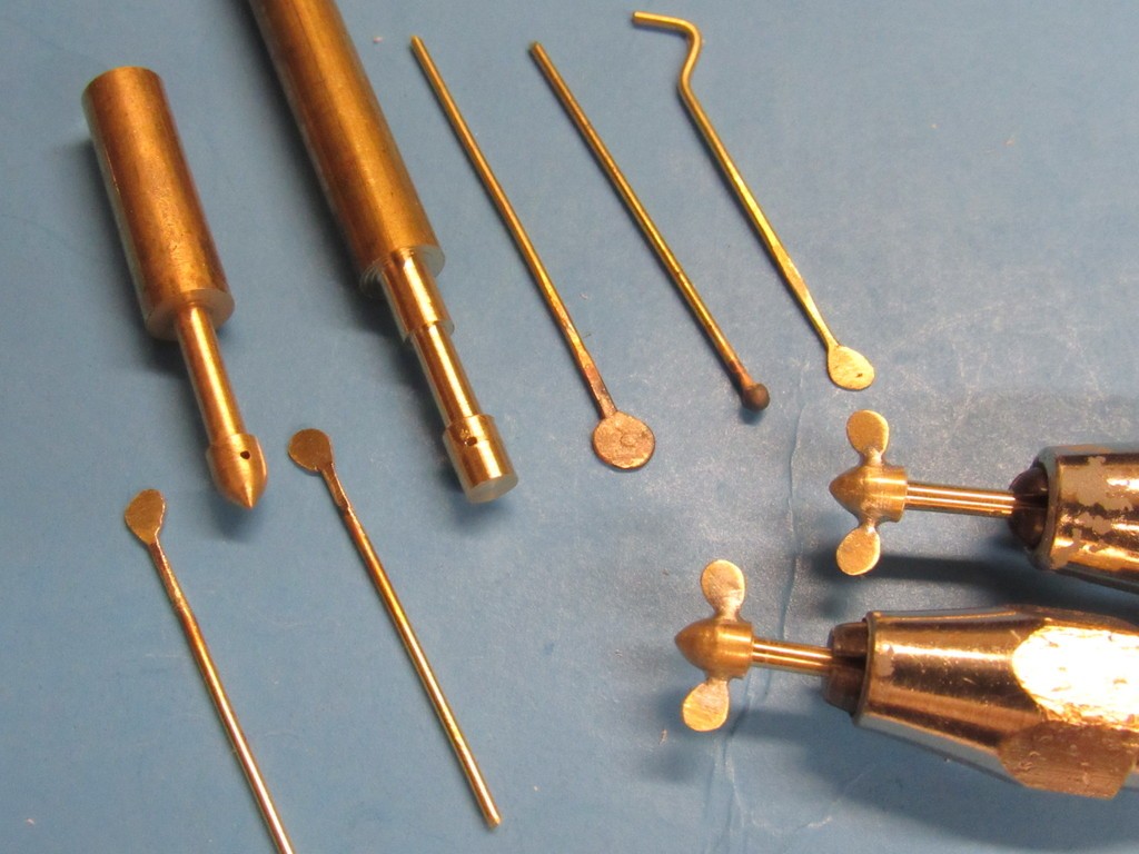
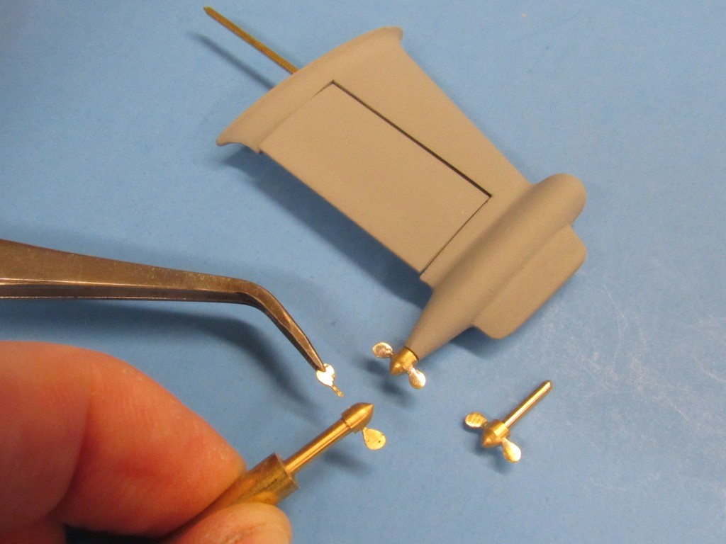
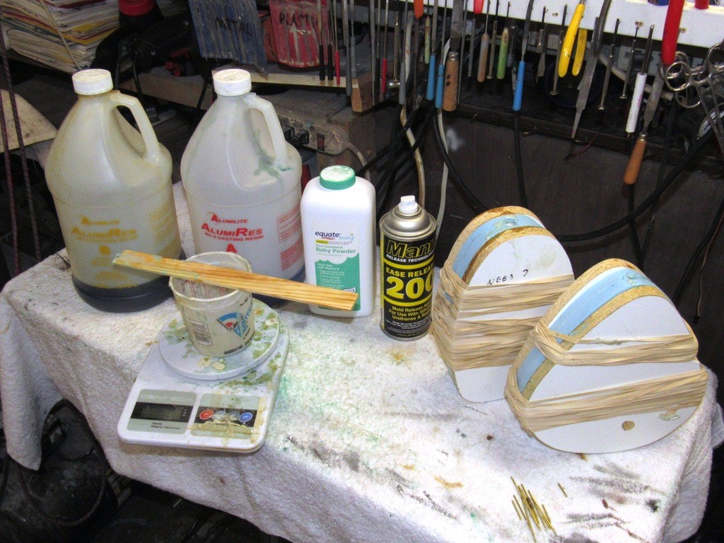
    In practice the cast white-metal propeller will be secured to its propeller shaft with a 4-40 X 1/4” long set-screw. About 1/8” of shaft will project aft of the hub and the cast resin dunce-cap will be a press-fit to that.

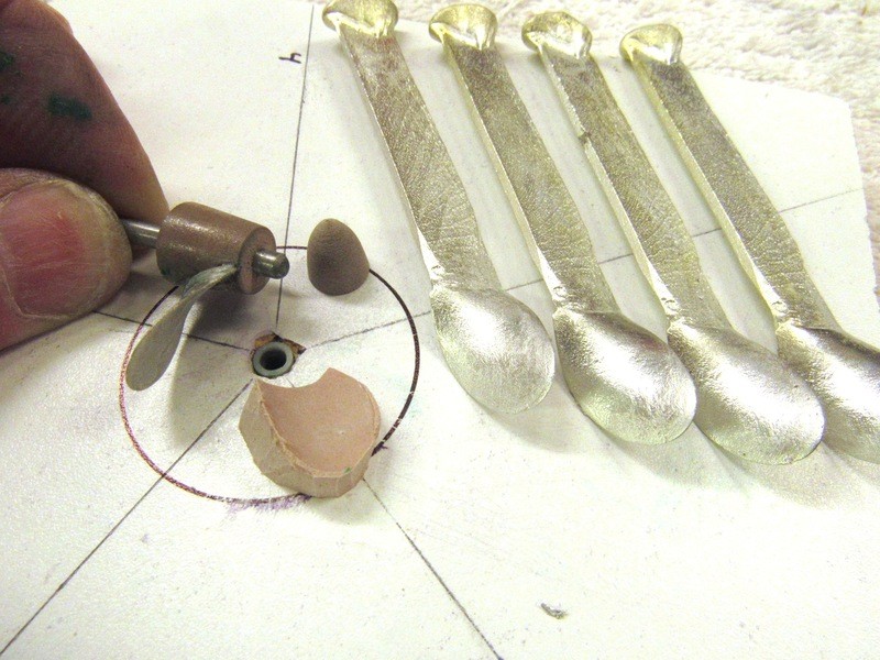
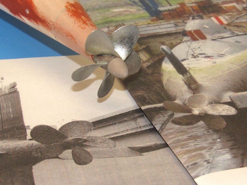
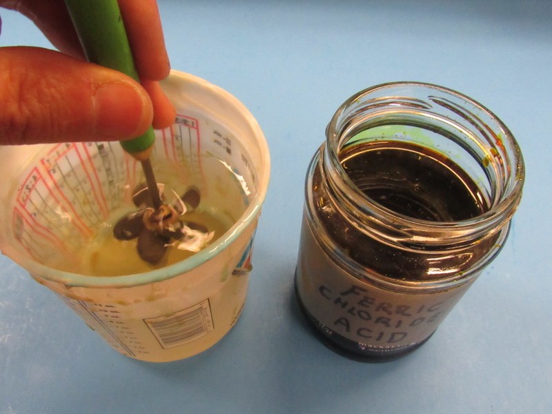
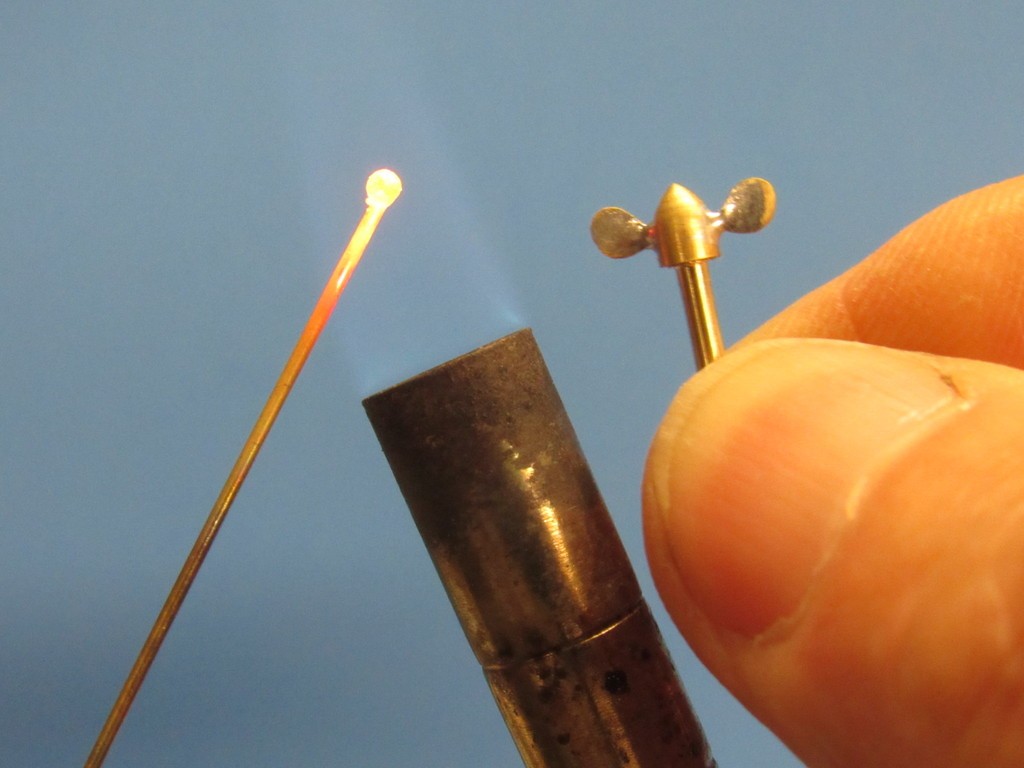
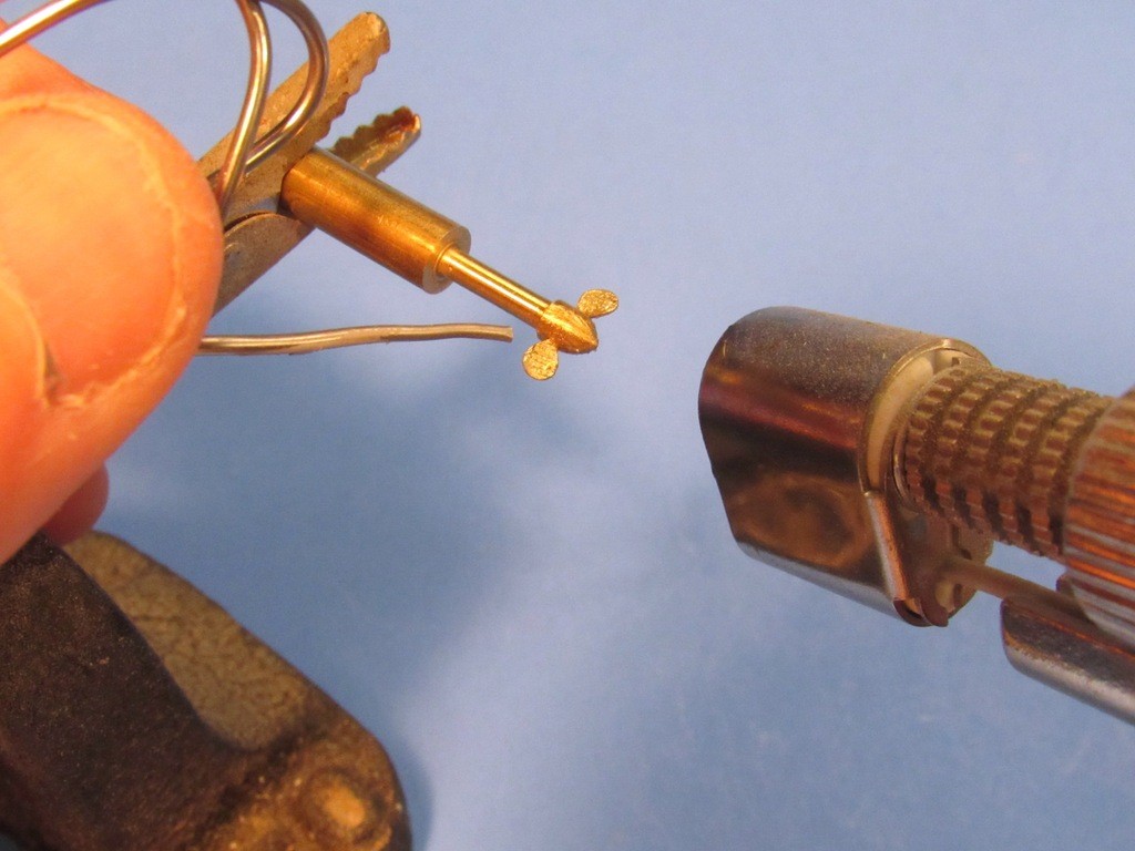
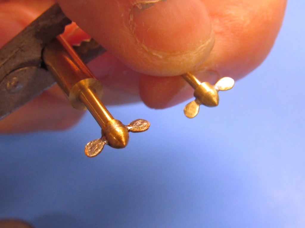
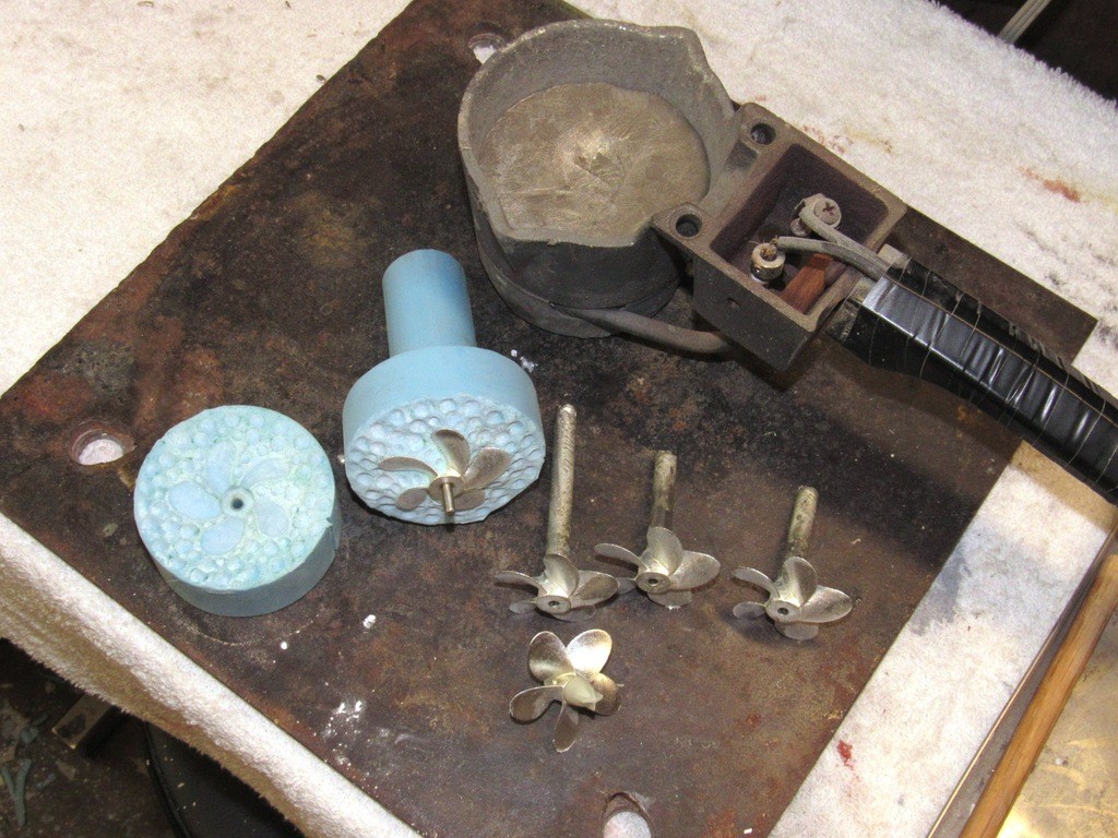
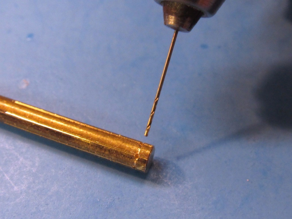
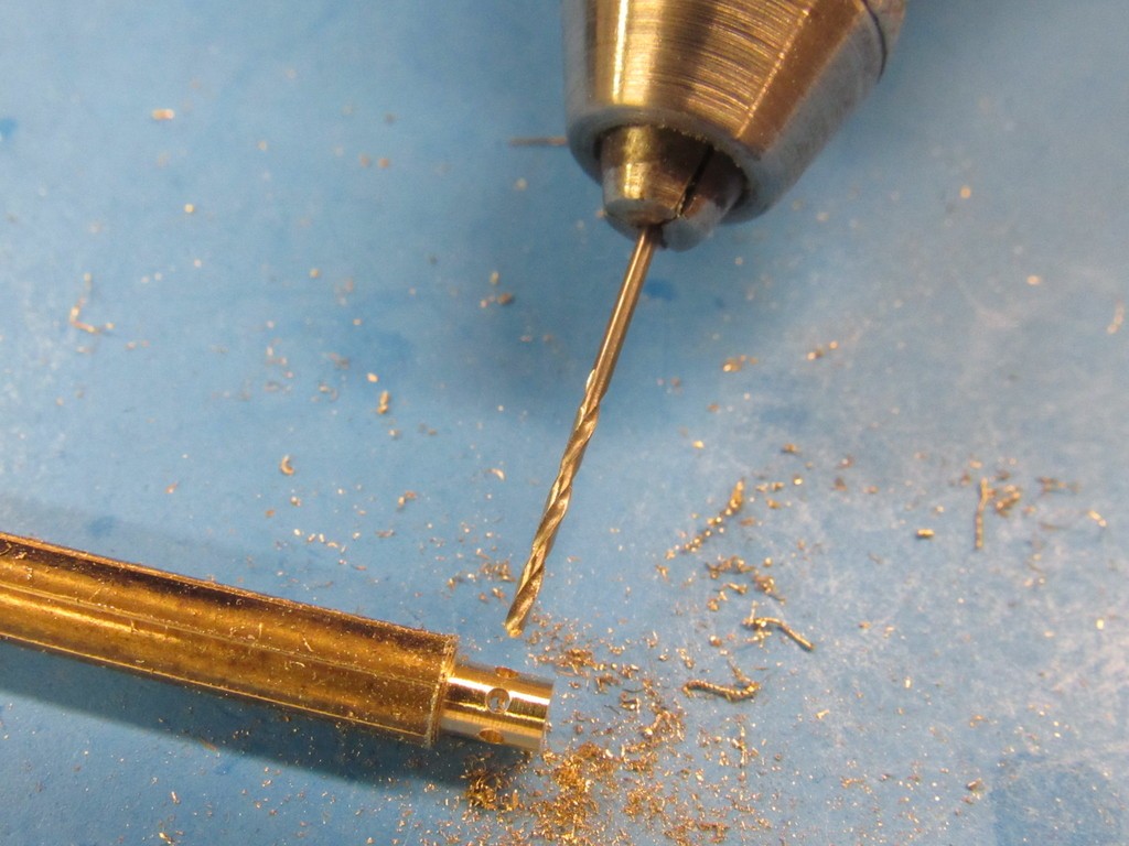
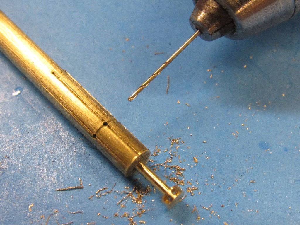
    Current task is making the little outboard propellers – used for in-harbor maneuvering and possibly as a back-up to the main running gear should a propulsion casualty occur.

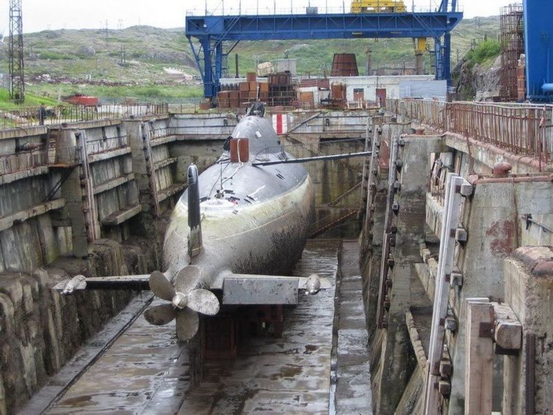
    It has been suggested that these direct-drive, electric motor driven propulsors might also have been used for ‘silent running’ in some tactical situations, but I’ve yet to read a reliable source saying so. The ALFA’s liquid metal cooled reactor could never be shut down to the point where the coolant changed state, so they needed primary pumps running all the time if any useful power-level was to be maintained. Knowing this I just can’t imagine the logic of this class of boat ever running silent on those two creeper-motors -- might as well expect to hear a pin drop at a KISS concert.

    upgrading the SSY 1/96 ALFA kit Hes5am


    merriman
    merriman
    Guest


    Posts : 347
    Join date : 2011-10-16
    Age : 75
    Location : Virginia Beach, Virginia

    upgrading the SSY 1/96 ALFA kit Empty Re: upgrading the SSY 1/96 ALFA kit

    Post  merriman Fri Aug 09, 2019 6:06 pm

    There’s awful looking model building. There’s just OK model building. There’s fine model building. Then there’s over-the-top-WTF-am-I-doing model building.

    We’ve all been there: you’re cruising along with a model job and you’ve got most of the hard work out of the way. Almost ready for paint, you’re looking forward to wrapping the project up so you can move on to the next job. Then, something grabs you: you start obsessing about the small shit – stuff you had not even considered when you prepared the project to-do list: you start counting the god damned rivets; your waking hours find your brain filled with an ever increasing list of things you can do to make the display better; the list of what next to do and how to do it even working its way into your sleeping thoughts.

    This project exemplifies. Too late I found myself in the grip of the dreaded, all consuming malady called, Advanced Modelers Syndrome. I blame the Malakhit Design Bureau, who designed this beautiful submarine back in the late 50’s. Somehow I caught a bad dose of AMS from those long dead, sneaky Commie SOB’s!

    upgrading the SSY 1/96 ALFA kit NwWKmD

    I came to the inescapable conclusion that the display would not be complete without the creeper/outboard propellers.

    OK, the angst out of my system. Moving on:

    (And let’s change that nomenclature – as the ALFA just was not at all stealthy, no matter what – let’s call these little propellers and their associated running gear, outboards).

    The use of such outboards is not unique to the Malakhit ALFA. You see similar units on their VICTOR’s and the single unit of the Rubin design bureau’s MIKE class. The little propellers, which are of the controllable pitch type, are represented as feathered -- the position they normally assumed, the blades offering minimal drag. When in use the outboard propellers would assume a pitch suitable for the direction and amount of thrust required.

    Below are the 1/96 scale horizontal stabilizers-stern plan masters equipped with the just completed outboard propellers, displayed over a picture of a dry-docked ALFA class submarine.

    upgrading the SSY 1/96 ALFA kit BWMqTf

    In the interest of imparting strength to small items, be they masters or display parts -- particularly items of thin section like these two propellers -- I typically fabricate from soldered brass, or machined from brass, wood, or RenShape; or cobbled together from commercially available extruded metal/plastic shapes and sheet. There’s nothing more frustrating than putting a lot of work into a sub-assembly only to have it later crumble in your hand at some later point. Mechanically robust, survivable masters and parts are at the top of my list of physical properties when I work out the fabrication methodology and materials selection.

    For these little propeller masters I elected to lathe turn the hubs from machine brass, and form the blades from a stamped .032” diameter rod of cartridge brass, bonding the three elements with common Tin-Lead solder.

    upgrading the SSY 1/96 ALFA kit Z5q7Jc

    To the extreme left is a turned hub with a transverse .015” hole drilled through it to accept the nubs at the base of the two .020” thick propeller blades.

    Center is a hub-in-the-making just after drilling the transverse hole and before the dunce-cap tapper is turned to shape. It’s easier to drill through a simple curve than a complex one.

    The three items at the upper right of the photo give up how I produce a propeller blade blank from a length of .032” diameter brass rod: The center rod has already had its end heated to the point of collapsing into a substantial ball of the metal; to the left of that is a ball hammered to a flat disc; and to the extreme right a blade part after being shaped with a fine carbide cut-off wheel and files.

    (Ben Guenther taught me to get into the habit of making more parts for a small project than you eventually need, as having those spares on hand forestalls frustration when one is lost to the floor, or you want to present a photographic record of process, like you see here).

    upgrading the SSY 1/96 ALFA kit MqzvMo

    If you heat the end of a brass rod to the point where the tip melts, the molten metal will fall back on the melting material under it, and the process will continue. The size of the molten ball will increase as long as the heat is maintained. Eventually a ball of metal, attached to its parent rod, is produced that is ideal for further shaping with hammer and anvil. This is how a propeller blade starts. In my hand is the end-game, a finished outboard propeller master.

    upgrading the SSY 1/96 ALFA kit C7pJTu

    On the face of this little anvil are before-and-after looks at how the hammer is used to mash flat the room-temperature ball of brass into a flat blank ready for profile shaping into a propeller blade part. The ball initially, because of the previous heating, is very soft and easy to shape. But, after a few healthy hammer blows the brass starts to ‘work harden’ and further blows would shatter the metal. So, periodically the work is taken to a red heat and allowed to naturally cool back to room temperature, once again softening the metal into malleability. The thinning-widening process continues till the blade blank, by now a disc and a bit thicker than the desired .020”, is achieved. Then, if required, the disc and stem are further hammered to get them to the desired rigidity necessary for the next step: shaping the disc to the profile of a blade.

    upgrading the SSY 1/96 ALFA kit YLGHbk

    Note that a substantial amount of the machine brass round-stock from which the hub was turned is retained and used as a convenient handle during the blade assembly.

    A small, unreinforced carbide cut-off wheel and files get the blade blank to a rough profile of the desired blade shape. The propeller blade stem is cut to a length that will reach half-way into the turned brass hub transverse hole, and the stem crimped as required to make it an interference fit within that hole. The two friction-fit blades are then prepared for soldering to their hub and the assembly set into the jaws of a holding fixture. Note that the blade angle is ‘zero’ to the longitudinal axis of the submarine, representing a feathered controllable-pitch type propeller, in the non-propulsive mode.


    upgrading the SSY 1/96 ALFA kit SgbzUs

    The entire assembly was slathered with acid type solder flux, heated, and Tin-Lead solder applied. Capillary action worked to not only draw the solder into the nub filled hub holes, but also produced perfect little fillets between blade roots and hub – some of which would later be shaved away, these propellers were, after all, supposed to be of the controlled-pitch type.

    upgrading the SSY 1/96 ALFA kit ZTUQbg

    Each assembled propeller was shaved, ground, filed, and sanded. Final smoothing was done by vigorous scrubbing with 0000-steel wool.

    Eye-strain city! God I was glad when those chores were done.

    upgrading the SSY 1/96 ALFA kit IhDs6i

    upgrading the SSY 1/96 ALFA kit Qnrp4C

    upgrading the SSY 1/96 ALFA kit MTstGw

    Once I had snipped the 1/16” diameter shaft equipped propeller hub away from the raw round-stock I employed pin-vices to serve as handles to hold the work.

    upgrading the SSY 1/96 ALFA kit 73z1ej

    And the finished outboard propellers, represented in the ‘feathered’ position. A dunking in Ferric chloride acid to oxidize their surfaces, a shot of primer, and they join the other masters that will be used to make a spin type metal casting tool. From that tool white-metal (Tin-Antimony) production parts will be produced.

    upgrading the SSY 1/96 ALFA kit 6NosPY


    upgrading the SSY 1/96 ALFA kit YzD1sU
    merriman
    merriman
    Guest


    Posts : 347
    Join date : 2011-10-16
    Age : 75
    Location : Virginia Beach, Virginia

    upgrading the SSY 1/96 ALFA kit Empty Re: upgrading the SSY 1/96 ALFA kit

    Post  merriman Tue Aug 20, 2019 2:15 pm

    After a few weeks of on-again-off-again ALFA work I’ve finally reached the point where the principle masters – the stabilizers, control surfaces, propeller, SubDriver foundations, Velcro strap foundation, indexing lips, forward propeller shaft bearing foundation, propeller dunce-cap, and secondary loop intake scoops – are completed. Now comes the job of using these masters to give form to the rubber tooling needed to produce cast resin parts, and white-metal propeller.

    I still need to finish the masters for a spin-casting tool that will be used to produce the white-metal detail parts, more on that work soon.

    Below I’m pulling masking tape from the top edges of the fillets at the base of each stabilizer – that tape in place during the final coat of primer to produce the desired raised edge. Tape and primer can also be used this way to represent just about any raised or inlayed item on a models surface you require. Such as plating; armor; weld-lines; oil-can dishing; access plates; diamond-deck; planking; and chipped paint, just to name a few high-relief detail items possible with the technique.

    upgrading the SSY 1/96 ALFA kit TwrIzL

    It’s been my experience that #0000 steel wool is the ideal abrasive to give a final cutting to simple and complex curves, such as the fillets of the horizontal and vertical stabilizers seen here. On occasion a 3M abrasive pad can be pressed into service for the same type job. However, I prefer the steel-wool because of its ability to be compacted into just about any shape and size needed for the job at hand, such as the deep troughs within the stabilizers, stabilizer to hull fillets, leading edges of the planes, and tight radius transitions between outboard motor fairings and horizontal stabilizers.

    upgrading the SSY 1/96 ALFA kit UKVukq

    Two tools are needed to produce the cast resin parts. Here I’m working out the best lay-out of masters over some decorative cardboard. The objective here is to minimize the amount of rubber employed to make the tool, yet insuring a lay-out that will assure proper venting of displaced air as catalyzed resin fills the tools cavities during the pour. Careful design here is EVERYTHING if consistently flaw-free castings are to be achieved during production.

    Why two tools and not simply one larger tool? The size and width of each tool and its accompanying strong-backs is limited to interior height and diameter of the pressure pots I use for resin casting.

    The masters to the left are the stabilizers and control surfaces, and this tool will feature a dedicated, centrally running sprue channel. The masters to the right, specifically the center ones, will produce cavities (the Velcro foundation and two SubDriver foundations) that not only give shape to the eventual resin, but will also do double-duty as sprue channels, off of which the outboard cavities will connect through runners to also receive the casting resin. Proper tool design is an acquired art.

    The masters are arranged atop the cardboard until an acceptable geometry is achieved and the outline of the eventual tool boarder is determined. At that point one side of the cardboard is penciled a line denoting that boarder. Since each side of the eventual tool is symmetrical to the other I simply have to fold the cardboard over and make one cut to achieve a stencil for mark-out of the mold-board/strong-back.

    upgrading the SSY 1/96 ALFA kit XGtAug

    The two pieces of cardboard were cut free from the sheet, folded in half at their sprue lines (centers), and scissors used to cut perfectly symmetrical templates.

    The propeller master was mounted on a vertically oriented 1/8” diameter shaft set into the center of a disc shaped piece of particle-board.

    upgrading the SSY 1/96 ALFA kit 44nxSr

    The cardboard templates are used to mark out a length of ¾” thick particle board shelf (which conveniently has a veneer of white plastic on each side). Each mold-board/strong-back cut to shape on the band-saw. These eventual strong-backs initially form the foundation for formation of the tools first half. Later, a second set of strong-backs will be cut to shape which will join the first set to sandwich the completed rubber tools, with the aid of rubber bands, during the resin casting operation.

    upgrading the SSY 1/96 ALFA kit Y5R391

    A two-part rubber tool starts by sinking the masters about half-way into some non-sulfur clay. The clay is heated under some bulbs till its nice and gooey, then rolled out on a mold-board/strong-back till it’s about 1/2” thick and flat.

    upgrading the SSY 1/96 ALFA kit Izvos8

    After all masters had been pushed approximately half-way into the masking clay wooden tools (the wood is softer than the primer of the masters, preventing damage to the finish) were used to pack the clay up tight against the sides of the masters. Final setting of the masters in clay was done with a stippling brush applied with plenty of water to keep the oil-based clay from sticking to the brush bristles.

    After the vent and runners were denoted with shallow engraved lines, the flange face of each clay mask was dimpled with brush handle ends – these dimples would eventually form negative and positive impressions on the eventual rubber tool halves, indexing them together in perfect registration. A light spray coat of mold/part release insured that the clay would not be lifted by the brush handle as I pressed the tool into the work.

    upgrading the SSY 1/96 ALFA kit Pol8cV

    With the propeller master sitting on its peg atop the disc shaped foundation, clay was worked under each blade, to completely mask the underside so no rubber could get at the bottom half of the propeller master. Final pushing-in of the soft clay was done with a wet, stippling brush.

    Note the wooden tool (formed from a Popsicle stick) used to do the initial clay packing under the blades.

    upgrading the SSY 1/96 ALFA kit 9aXPrL

    Containment of the rubber for the propeller was simply a short length of Lexan cylinder. For the two large mold-boards I used non-sulfur bearing masking tape -- wrapped around the circumference of each mold-board -- to contain the RTV silicon tool-making rubber as it changed state from liquid to semi-solid.

    upgrading the SSY 1/96 ALFA kit CvjL88


    avatar
    timgarrod
    AMS Website Webmaster


    Posts : 259
    Join date : 2013-04-23
    Age : 43

    upgrading the SSY 1/96 ALFA kit Empty Re: upgrading the SSY 1/96 ALFA kit

    Post  timgarrod Tue Aug 20, 2019 9:46 pm

    Nice work there :)

    looks brill
    merriman
    merriman
    Guest


    Posts : 347
    Join date : 2011-10-16
    Age : 75
    Location : Virginia Beach, Virginia

    upgrading the SSY 1/96 ALFA kit Empty Re: upgrading the SSY 1/96 ALFA kit

    Post  merriman Thu Aug 22, 2019 12:53 am


    Time finally came to complete the rubber tooling used to make the resin production pieces.

    After the RTV silicon rubber of the first half of the two tools had cured hard, it was pulled off the masking clay and imbedded masters. You can see to advantage here how the surface of the masking clay produces the flange face of the tool half. The array of positive dimples in the rubber tool halves will produce matching depressions when the second half of the tools is poured. Note that the propeller has already been removed from its masking clay, cleaned up, and installed in the first half of its tool.

    upgrading the SSY 1/96 ALFA kit CLh0aN

    All master pulled from the masking clay, cleaned up, and mounted within their respective tools. The tool half to the left makes use of a brass rod to form the centrally running sprue, The tool half on the right makes use of the high cross-sectioned Velcro foundation and SubDriver foundations as sprue place holders.

    Masking tape will be wrapped around the two tool halves forming the flask that contains the liquid rubber till it changes state to a solid. The propeller flask is simply a short length of Lexan cylinder.

    To prevent the flange faces of the halves from permanently sticking together, the flange face of the first tool half is given a generous coating of Mann 200 part-mold release.

    upgrading the SSY 1/96 ALFA kit GefAZc

    Pouring catalyzed RTV rubber to form the second half of the two big resin casting tools.

    If the resin casting process involves subjecting the resin to one or two atmospheres of pressure during the cure then it’s vital to eliminate bubbles from the mixed rubber during the tool making process. If bubbles remain in the rubber as a consequence of entrapped air from mixing then those bubbles, in the completed tool, will collapse under pressure, resulting in positive dimples on the surface of the cast resin pieces. Can’t have that!
    So, the RTV mix has to be de-aired before it hardens. I do this by subjecting the rubber mix to a hard vacuum. However, an alternative is to pressurize the mix after it’s been poured over the masters – hard to do! I prefer the vacuum de-airing scheme.

    The vacuum works to enlarge entrapped bubbles in the still liquid rubber to a size where they become super-buoyant, rise to the surface of the mix, pop, and the released gas extracted by the vacuum pump. The work then continues at normal atmospheric pressure.

    The pressure scheme, on the other hand, crushes entrapped bubbles back into solution. The pressure method of bubble elimination requires the poured rubber to be maintained in a pressurized environment for the duration of the state change – OK if you have NASA sized facilities, unrealistic if you’re working out of a converted single-car garage.

    upgrading the SSY 1/96 ALFA kit LdamM6

    Onto the surface of the masking clay I had lightly scribed in lines denoting were the runners (that lead from the main sprue channel to the individual tool cavities) and vent channels would be cut into the face of the flange faces. Here I’m doing just that with a collection of different sized circular gouges and knife.

    Note that at the top of the sprue (in foreground) has been dug out to form a reservoir – this cavity will contain make-up resin to maintain the head of resin in the sprue once the pressure pot is buttoned up and I can’t get to the tool with make-up resin. Under pressure any entrapped air remaining in the tool cavities after the initial pour will be crushed into solution and the extra resin in the reservoir will fall into the sprue making up for what the formerly entrapped air displaced.

    Either side of the sprue hole are vents that connect to vent channeling that extends over the tools flange, each branch of which vents the high point of each cavity.

    upgrading the SSY 1/96 ALFA kit H3y96W

    My favorite polyurethane casting resin is Alumilite RC-3. This quick-cure, economical, easy to work material is mixed 50-50 by weight and cures to a tan color. Check it out: https://www.alumilite.com/store/p/665-AlumiRes-RC-3-Tan.aspx

    With all the runners and vent channels cut into the flanges each half of the tool was given a coating of Mann 200 mold-part release spray followed by a good powdering of either corn starch or talc powder. The powder is distributed evenly onto the surfaces of the cavities by temporarily holding the two halves of the tool together and vigorously slamming it on the table, then opening the tool up and dumping the excess powder on the floor. This results in a fine, evenly distributed film of material adhered to the silicon part-mold release. The powder acts as a wick to pull the casting resin into the tightest of cavities within the tool, insuring a complete casting no matter the geometry or size of the cavity that gives form to the eventual cast resin part.

    Shards of carbon fiber were laid into the stabilizer and capture lip cavities. The eventual stabilizer parts need strength as their high aspect ratio make them susceptible to breakage in collisions (yes, I’m an ‘aggressive’ driver … sue me!), hence the reinforcement. The capture lips need the stiffening as they are under considerable shear force when doing their jobs of holding the two hull halves in alignment.

    I did two test shots with these two resin casting tools using rubber-bands to tightly sandwich the two-part tools between their strong-backs. These test shots revealed that, no matter how many rubber- bands were employed, they did not prevent excessive leakage of resin over the flange faces; there was not enough clamping force to minimize the formation of significant flash.

    upgrading the SSY 1/96 ALFA kit MCUwz7

    Here I’ve opened up the tools after removing them from the pressure pot. Note the carbon fiber shards imbedded within the capture lip and stabilizer parts. You see to advantage here the sprue, runner, and vent channel networks needed to introduce the liquid resin and vent the displaced air from the cavities that give form to the resin as it changes state from a liquid to a solid.

    upgrading the SSY 1/96 ALFA kit H3Hs43

    Even with all those rubber-bands used to clamp the tool halves together I still found too much flash around the cast parts. So, I abandoned the rubber-bands in favor of a stud-and-nut clamping arrangement. Note that the studs pass through holes punched into the unused portions of tool. Location of each stud determined by examination of the rubber-band secured parts, placing a stud where the flash was the worst. Though this method of tool clamping is a bit involved to establish, the actual production work goes much faster than if rubber-bands were employed. A good investment of time and effort for tools that will see significant production runs.

    upgrading the SSY 1/96 ALFA kit 28ne0h

    This is the first shot using the stud-and-nut clamping arrangement. Note the absence of excessive flash around the cast resin parts. Brass rod mandrels were installed before casting to give form to the bores within the stabilizer and control surface parts.

    upgrading the SSY 1/96 ALFA kit KwFGv0

    The casting on the left, done with the stud-and nut clamps has significantly less flash around the parts, runners, and vent channels. Note the excessive flash on the casting on the right, clamped with rubber-bands. Minimizing flash produces parts that are easier to clean and are more dimensionally faithful to the masters than parts cast in a leaky tool.

    upgrading the SSY 1/96 ALFA kit G9nI9H

    The same BJB, TC-5050 RTV silicon rubber I use to make tools for resin casting is also tolerant of the heat involved with low-temperature metal casting. Here that same type rubber is used to make the tool that produces the white-metal propellers and small detail parts.

    upgrading the SSY 1/96 ALFA kit CCyIvf
    merriman
    merriman
    Guest


    Posts : 347
    Join date : 2011-10-16
    Age : 75
    Location : Virginia Beach, Virginia

    upgrading the SSY 1/96 ALFA kit Empty Re: upgrading the SSY 1/96 ALFA kit

    Post  merriman Sat Aug 24, 2019 6:11 pm

    Now that the tooling for all the cast resin parts is done and I’ve got some good castings from them it’s come time to complete all the masters needed to produce the spin-casting tool from which the white-metal detail pieces will be produced.

    In support of those tasks I’ve spent the last few days scribing in the engraved lines representing the hatches atop the sail used to fair over the retracted radar-ECM, DF, scope, and bridge wells. While at it I also engraved the outline of the escape-pod break between its fairing and sail.

    Capturing the compound curves unique to each station, I laid up a thin-walled GRP laminate. These blanks capturing the engraved lines, denoting where each hatch would be cut away from the surrounding GRP material.
    The dead-light openings where also punched out on the bridge wind-shield.

    But, first, I had to mark off the radial, horizontal, and oblique lines that defined the hatches and escape pod fairing outlines with a pencil – these lines guiding me as I scribed in the hatch and fairing outlines. To achieve symmetry I worked a waterline tool off the vertical and horizontal datum planes established by a holding fixture.

    Radial lines were achieved by sliding the waterline marking tool along a vertical fence whose face is oriented perpendicular to the models longitudinal axis. Setting the distance of the pencil lead from the face of the fence denoted the radial edges of a hatch as well as its pivot-pin extensions.

    upgrading the SSY 1/96 ALFA kit WIHk8R

    Horizontal lines were marked using the flat surface of the holding fixture as the horizontal reference plane. The height, length and position of each horizontal, vertical and oblique line lofted off the 1/96 plan you see mounted on the wall.

    upgrading the SSY 1/96 ALFA kit OlCx5l

    The gel-coat on this models GRP hull was a joy to work with: hard enough to tolerate drilling and cutting without gumming up, yet soft enough to permit easy scribing with saw tip, knife, and scribe. First I cut in the straight radial, horizontal and oblique lines. Then the more exacting work with knife and scribe to gouge out the hinge pivot-pin extensions and bridge deadlight outlines. One is advised to abstain from caffeine drinks prior to this type work.

    Note the tool to the extreme right: A small piece of razor-saw has been chucked up in a standard X-Acto knife handle. This tool gives me the ability to cut a straight or slightly curved engraved line without aid of stencil or straight-edge -- very useful in some situations, like those little pivot-pin extensions at the bottom edge of the two mast hatches.

    upgrading the SSY 1/96 ALFA kit HiZwre

    Documentation is everything! But only trust photos of the actual prototype. Plans (orthographic, isometric, and scrap-views) are generated by humans and are subject to error. However, photographs don’t lie or are subject to accidental error. Even source documents, such as Ships General Arrangement and Docking plans have the occasional dimensional or form error … and don’t get me started on the all-too-often plan-profile-section paradoxes discovered when attempting to generate waterlines and buttock lines.

    Note the use of commercial scribing stencils. I made good use of these as I cut in the tiny pivot-pin extensions and deadlight outlines.

    upgrading the SSY 1/96 ALFA kit UmmoAl

    Overstrikes, cheat-lines, corrected lines, and other boo-boos were filled with Nitro-Stan putty and sanded smooth – this step repeated many times until only the desired engraved lines remained atop the sail. It’s vital that before the putty dried the desired engraved lines are chased out with a scribing tool to preserve the work.

    The ‘finishing’ scribing tool differs from the first-pass tool in that it features a rounded tip and a shank a few thousand’s of an inch smaller in diameter than the first-pass tool. It’s the job of the finishing scribe to chase out filler and sanding dust, not to continue to cut depth or width of the engraved line.

    upgrading the SSY 1/96 ALFA kit RBuYeF

    At this point the work looks like hell.

    The long oblique lines on the sides and running around the top of the sail represents the break between the sail proper and the plating that fairs beneath it a deployable ‘rescue chamber’.

    (In the event the crew has to abandon the sunken submarine they would all jam up into this pressure sphere, located beneath the bridge, button it up, and release it from the submarine. It would then float up to the surface where the men would transfer to inflatable rafts and await rescue. The system actually … kind of … worked when a Soviet MIKE class submarine grounded after a fire and subsequent sinking.)

    upgrading the SSY 1/96 ALFA kit 1aSWkd

    A quick shot of primer gray reveals an acceptable looking engraving job.

    The biggest sin with this kit is the awful engraved detailing atop the hull and sail. Misshapen, out-of-place, and not conforming to any reliable documents I have been able to unearth – and I don’t think anyone this side of the Malachite Design Bureau has more dope on this boat than me!

    The only trustworthy original engraving on this kits hull is the torpedo tube shutter doors, and those will have to be cleaned up and deepened. Ah! The Joy of kit assembly!

    upgrading the SSY 1/96 ALFA kit IhOMNH

    Now, this is where I go bat-shit (yet again!) with a project that was only supposed to take a few weeks of my precious time. Your idiot author decided to produce two sets of auxiliary hatches, one set representing closed hatchs (to cover open wells and/or open bridge cockpit); and another set of port and starboard hatch halves to be mounted on the model to compliment the display of masts and scopes in the raised position, and an opened bridge well.

    The masters of the off-model hatches would be GRP, that material chosen because of its ability to faithfully capture, exactly, the compound curves of the hatches; and to render strong, thin-walled structures. Those intermediate masters would be used to make an intermediate tool from which production masters would be produced – detailed inside and out and split into their respective parts. Only then would the two sets of hatches we employed to make the production spin-casting tool from which all the detailed small bits of the display would be manufactured from white-metal (95% Tin, 5% Antimony).

    But, before all that, I had to lay down a protective barrier of wax and poly-vinyl alcohol over the top of the sail. The same part-release system as would be used for your typical hard-shell GRP part lay-up. Old school… by cracky!

    upgrading the SSY 1/96 ALFA kit Tj1Gdj

    To keep any of the laminating resin from running down onto the hull I laid down masking tape to the sides of the sail. The part-release system applied, some light-weight glass cloth squares cut out and set aside for the lay-up job.

    upgrading the SSY 1/96 ALFA kit 04zqmw

    The never-fail West System epoxy laminating resin was mixed up, and I laminated four layers of one-ounce glass cloth over the three mast hatches and bridge enclosures.

    upgrading the SSY 1/96 ALFA kit RFv2Yy

    I did manage to damage some of the engraved work when I pulled the cured GRP blanks off the sail. But, it was all quickly fixed with putty and the finishing scribe, followed by a careful wet sanding. You can see here how the engraved lines of the sail, now relatively high-relief positive lines on the underside of the blank, capture perfectly the outlines of the hatches. I followed those lines as I cut each hatch intermediate master to shape.

    upgrading the SSY 1/96 ALFA kit TzaRHP

    After the lay-up atop the sail, and before the epoxy mix changed state, I thickened it with some talc, scrubbed the entire upper hull with a lacquer thinner drenched 3M abrasive pad, and dabbed the goo over all of the model hulls original engravings (except the torpedo tube shutter doors). After the epoxy had cured hard I filed and sanded the work down flush with the surface of the hull. From this point I could re-scribe the hull with a more accurate representation of access hatches, doors, salvage fittings, and the like.

    upgrading the SSY 1/96 ALFA kit YWCsBw


    merriman
    merriman
    Guest


    Posts : 347
    Join date : 2011-10-16
    Age : 75
    Location : Virginia Beach, Virginia

    upgrading the SSY 1/96 ALFA kit Empty Re: upgrading the SSY 1/96 ALFA kit

    Post  merriman Thu Aug 29, 2019 6:50 pm


    After popping off the GRP sail hatch blank from atop the sail I inverted it and followed the raised hatch outlines to cut each hatch assembly away from the surrounding GRP material. This shot of that nearly completed task shows the intermediate master hatches laid over a good shot of a prototypes sail.

    I’m well underway here with punching out the openings for the bridge windscreen deadlights.

    upgrading the SSY 1/96 ALFA kit OAzPiL

    What will become the hatch intermediate masters are test-fit atop the sail to insure I have their orientation correct as I carefully match their outlines to those of the engraved lines atop the sail.

    Check twice cut once, as they say.

    (I assume that the forward hatch fairs over the boats snorkel induction mast – the one with the arrow on it. I can’t find any documents stating its function. Is there anyone in the audience who can give me a definitive answer to that question??).

    upgrading the SSY 1/96 ALFA kit TF5JVu

    GRP, once cured hard, is a total bitch to cut and saw. The best tool for parting this material is a carbide cut-off wheel. For small, fiddly work like this I use the thinnest, unreinforced carbide wheel available, spun at high RPM’s. (Don’t forget the eye-protection as these things WILL shatter, spewing shrapnel everywhere when they explode in your face). Final shaping is done with diamond files and stiff sanding sticks.

    I’ve found the best tool for roughing out holes in the center of GRP laminates is an old drill bit pressed into service as a poor man’s router bit. High speed, carefully applied lateral pressure, and luck produce a hole of approximate size and shape. The work is finished with knife, carefully selected and skillfully used jeweler’s files (sometimes modified as you see here), and purpose built stiff sanding sticks.

    upgrading the SSY 1/96 ALFA kit MzHs0M

    Once these intermediate hatch masters were cut to outline, they were given a final coat of primer and lightly abraded with #600 sandpaper used wet. They were then set into masking clay and the first half of a two-part rubber tool was poured. We’ve all seen that movie … moving on.

    upgrading the SSY 1/96 ALFA kit Q2Ymp6

    The initial plan was to use this intermediate tool to produce cast white-metal production master.

    ‘Best laid plans of mice and men OFTEN go astray!’

    Sure, these .025” deep cavities would present a lot of back-pressure to any filling medium, but I figured a tall sprue pipe – gravity producing a significant pressure-head that would force the liquid metal into these tight cavities – would get the job done. But, after many shots, ever increasing the height of the sprue pipe, and much foul language I could not get complete fills of the cavities. Round one to Murphy!

    So, I switched gears and elected to cast GRP reinforced polyurethane and epoxy laminates in this tool. To insure a complete evacuation of all air within the cavities I employed the vacuum casting technique (yes, I’ve written about that, check past WIP’s). I got quick turn-around with the polyurethane resin glass reinforced pieces, but they (even with the encapsulated glass cloth) were soft and easily distorted by handling. Fortunately the epoxy units were found to have the properties I wanted: chemically stable, strong, and shape retention no matter how roughly I handled them.

    Now, with several sets of suitable production masters in hand, I could proceed with one set to close open wills, and the other set to represent the hatches in the open position.

    upgrading the SSY 1/96 ALFA kit LjDmsu

    At my core I’m still a navy trained, ham-fisted, I-can’t-spell-it-but-I-can-lift-it Torpedoman. So, I did not trust myself to hand-hold this fiddly work. Here I’m producing conformal holding fixtures out of Bondo.

    The process was easy: A catalyzed goop of Bondo was dumped on a scrap piece of shelving board; a piece of clear packaging wrap placed atop the goo to isolate the masters from the Bondo; and an intermediate master pushed into the muck and held down tightly (note the big file tang with a glued on popsicle stick ‘finger’ pushing a master down into the Bondo) as the filler changed state from stinky goo to solid.

    upgrading the SSY 1/96 ALFA kit JutPMm

    And here are the holding fixtures in use. I’ve shaved away excess Bondo and have separated each holding fixture to make handling of the separate production master hatches an easier task.

    upgrading the SSY 1/96 ALFA kit 7QM1Hp

    To the left is the ‘closed’ production master for the three-piece bridge well closure; to the right I’m working the ‘opened’ windshield portion of the bridge well. These will join the other hatch production masters when it comes time to fabricate the disc-shaped spin-casting production tool used to make the small, detailed, white-metal fittings that go with the 1/96 ALFA fittings kit.

    Though this shot gives some appreciation at how small the work is here, it’s not completely accurate. In practice I secure the hatch half atop the sickly side of a piece of double-stick tape (in some circles, sold as ‘servo tape’). That double-sided sticky tape secured to a piece of scrap shelf-board much like I did with the above holding fixtures. I handle the piece of shelving board in my massive rat-like paws rather than the tiny work itself. I’m old and shaky. Sue me!

    Yes, the stringers and frames look to be much too big – and they are. These .020” thick pieces are best handled when over-size in height. Later, after all the pieces have been CA’ed within the production master they will be ground down with moto-tool sanding drum and cylindrical sanding ‘blocks’. Their heights reduced to a mean .020” which then gives them the appropriate ‘square’ section you see on prototype.

    upgrading the SSY 1/96 ALFA kit CZLHUC

    A sneak-peak at the eventual end-game to this madness: the creation of two sets of sail hatches. One set to cover the wells under an opening; and another set – each hatch split into two pieces – representing opened hatches. I’ve already done that work with the bridge windscreen and clamshell hatch halves, as well as outfitting these with .020” square stringers and ribs. The DF and radar-ECM well hatches are aft and are yet to be split and detailed with framing and actuator clevises.

    I previously neglected to mention the extreme forward square hatch, which does not split like the others but swings up and is hinged on the starboard side – its practical function to fair over the well from which the snorkel (pending clarification) induction mast resides. At this point that hatch has been outfitted with framing as well as two clevises which make up to the hydraulic actuators that open and close the hatch.
    Note that at the extreme left is a start of the DF antenna production master.

    upgrading the SSY 1/96 ALFA kit A2PCbl

    A quick look at the work done so far on the DF antenna: This particular one – seen on every ALFA I’ve found a picture of – has the atypical six part antenna rather than the simpler four part DF antennas seen on most other Soviet … err …. Russian submarines. The guys at the Malachite Design Bureau did this just to fuck with me! How did they know?

    Some minor-league machining involved with this unit. I’ll go into detail on that later.

    God!! Will this job never end???????????

    upgrading the SSY 1/96 ALFA kit QAK67m


    salmon
    salmon
    AMS Forum Owner


    Posts : 312
    Join date : 2011-09-02
    Age : 64
    Location : Las Vegas, Nevada - USA

    upgrading the SSY 1/96 ALFA kit Empty Re: upgrading the SSY 1/96 ALFA kit

    Post  salmon Thu Aug 29, 2019 10:46 pm

    Absolutely astounding. In a 1,000 years, I do not think I will come close to your skills David. Thank you for taking the time to share. I know how much time that takes to get the photos, prepare them for the web, and put enough description to make it useful in explaining what is going on. I so appreciate your work and efforts to share what was taught to you (with interest). Thank you.


    _________________
    If you can cut, drill, saw, hit things and swear a lot, you're well on the way to building a working model sub.
    merriman
    merriman
    Guest


    Posts : 347
    Join date : 2011-10-16
    Age : 75
    Location : Virginia Beach, Virginia

    upgrading the SSY 1/96 ALFA kit Empty Re: upgrading the SSY 1/96 ALFA kit

    Post  merriman Thu Aug 29, 2019 11:25 pm

    salmon wrote:Absolutely astounding. In a 1,000 years, I do not think I will come close to your skills David. Thank you for taking the time to share. I know how much time that takes to get the photos, prepare them for the web, and put enough description to make it useful in explaining what is going on. I so appreciate your work and efforts to share what was taught to you (with interest). Thank you.

    Thanks, Tom. You too have a good set of hands. So, the complement has merit and is appreciated.

    Most of us are responsible fathers and spouses who balance model-building with real-world obligations. It takes a very special (borderline psychotic) drive to make the Craft your personal-professional obsession. The willingness to neglect all activities that interfere with the Craft. It's that kind of crazy drive that makes a Master in the hand-crafts. Total commitment. Selfishness is good.

    I knew at age six what I was going to do with my life. My only departures from the Craft was the pursuit of food, shelter, a pay-check, and a wife to satisfy my mortal needs. All else is model-building.

    You don't need 1,000 years, Tom. All that is required is a fit body, reasonably good genes, ruthlessness, and near total commitment.

    David
    The Horrible
    merriman
    merriman
    Guest


    Posts : 347
    Join date : 2011-10-16
    Age : 75
    Location : Virginia Beach, Virginia

    upgrading the SSY 1/96 ALFA kit Empty Re: upgrading the SSY 1/96 ALFA kit

    Post  merriman Sat Aug 31, 2019 3:35 pm

    Just quick looks at the hatch work this installment. Stand by for (drum roll, please) … machine lathe work 101.
    Specifically, how to index equally spaced spots around a cylinder. All that work in support of building the parts for a six-lobe DF antenna master.

    Here’s I’ve finished inserting all the polystyrene sheet stringers, frames, and ribs within the underside of the various ‘opened’ hatches and windshield masters. I’m applying Nitro-Stan putty with a brush to fill any gaps between framing and hatch edge. To hold the work as I brushed on the putty I used double-stick ‘servo tape’.

    At this point I was thoroughly sick of all things hatch master and gladly shifted my efforts to the antenna masters.

    (Great! Now that one’s in the bag I’m thoroughly sick of antenna master! …)

    upgrading the SSY 1/96 ALFA kit Y4NTr2

    Time had come to make the masters for the combined snorkel-antenna mast, periscope head, combined radar-ECM (NATO code name, brick pulp) antennas, HF antenna, and DF loop antenna (NATO code name, park lamp).

    Ever the masochist I started with the most difficult item: the direction-finding loop antenna, park lamp. The Soviets have employed variants of the DF antenna over the years. Park lamps featuring four, six, and as many as eight lobes observed on various classes of diesel and nuclear powered submarines.

    Each [-shaped lobe anchors at two hubs at the center of the antenna. The ALFA makes use of the six-lobe type DF antenna. So, I did the lay-out, worked out a methodology, selected appropriate materials, and got to work.
    The results you see here, a mocked up park lamp DF antenna. In practice only two lobes will be attached to the hubs and the other lobes, as well as the disc, will be separate items – concessions to the metal casting process employed to make production parts.

    Material selection is everything with this kind of work. Successful model-building is a sound understanding of the physical properties of the materials you work, and the best practices and tools for working the material in hand.

    Machine brass (an alloy of copper, zinc, and lead) was selected for the turned parts. The much harder Cartridge brass (a straight copper- zinc alloy, with a bit less zinc) that can be cold formed to a substantial degree without breaking would be the brass alloy of choice for the lobes. I found .032” rod was ideal for that task.

    upgrading the SSY 1/96 ALFA kit 6vvZht

    Here I’m marking the six, equally spaced, axially running lines along the machine brass round-stock that would eventually be turned to become the foundation (two hubs and connecting rod) for the six lobes of the DF antenna master.

    upgrading the SSY 1/96 ALFA kit TbQJzr

    The lathes power plug is pulled from the wall – the work is only turned by hand during the following axial line marking steps.

    The indexing plate (made this one myself: a dark stormy night, nothing to do, a protractor and a scrap sheet of styrene whispering my name from the shop – it was inevitable!) was liberated from another machine-tool and pressed into service for this particular job. You see the just marked out axially running engraved lines on the work, a length of machine brass (an alloy of copper, zinc, and lead) round-stock. This is the first step in transforming the work into a single piece comprising the lobe hubs, connecting rod, and shank of the DF antenna master.

    Those engraved axial running lines scratched into the work by simply running the cross-slide back and forth on the bed (Z-axis) after first lining up the reference point (the tip of a machinists surface gauge secured to the bed of the lathe) on one of the six equally spaced lines radiating from the center of the indexing plate.

    Six times the chuck was rotated by hand till a radiating line on the indexing plate intersected the indexing point; the chuck held fast; and, the tip of the tool just touching the surface of the stock, the cross-slide cranked along the Z-axis, engraving a line. The result is six equally spaced lines running the length of the work. Each axial engraved line, where it crossed a radial engraved line, denoted where I would drill the holes that would become the hubs.
    Before removing the work from the lathe I powered up and spun the work to dig a shallow radial grove near the end of the rod. This denoting the sectional plane through which six holes would be drilled.

    upgrading the SSY 1/96 ALFA kit Qtc7BQ

    A completed park lamp antenna master illustrates what the end game will be, providing some sanity to the discussion here.

    At the intersection of the axially running lines and radial line I punched indentations to guide a drill bit as I started the holes at the two hub locations. The work has yet to be turned to the correct diameter of the hubs – it was easier to work the bigger diameter stock than it would have been had I first turned to the smaller diameter and then tried to maneuver my fat fingers as I drilled the holes.

    upgrading the SSY 1/96 ALFA kit Sz0w9K

    The lobes are bent from .032” diameter rod, so eventually the hub holes will be bored to that diameter. But, initially pilot holes of .020” were bored out. This permitted me to correct any misalignment of bore spacing before committing to the final bore diameter. Check twice, cut once!

    upgrading the SSY 1/96 ALFA kit A4EXer

    Once the six holes were drilled I placed the work back into the lathe chuck and turned the hub to the desired diameter. WITH GREAT CARE – things break easily at this stage.

    Off-lathe the hub holes were bored out to the final .032” diameter. The work was then placed back onto the lathe were I very carefully began to turn the thin connecting rod between hubs to its correct diameter.

    upgrading the SSY 1/96 ALFA kit Y4yRKr

    Before turning the lower lobe connection hub to final diameter the upper lobe connection hub turned to final shape, and only after that is half of the slim connecting rod between the two hubs is turned to correct diameter.
    At that point I removed the work and drilled the six holes where the lower hub would eventually take shape.

    upgrading the SSY 1/96 ALFA kit I50LvA

    When turning flimsy items like this you endeavor to maintain as much of the work as close to the jaws of the chuck as possible – once something has been reduced to the required size, the work is pulled away from the chuck only to the degree needed to complete the next phase of the turning. Long, delicate things like this beak or bend easily when pressure is applied by the cutting tool. A steady-rest (thumb and forefinger in this case) helps to absorb the transverse force presented by the tool when the works section gets critically small like this.
    An acquired skill … I can assure you!

    upgrading the SSY 1/96 ALFA kit SmY0MA

    Martian’s may do things in three’s. Me? I sometimes do them in two’s. Three reasons why I made two DF antenna masters for this project:

    1. That’s the way Ben Guenther does his miniature work! http://www.missing-lynx.com/gallery/small/tigeri144bg_1.html

    2. Photo essays like this are more informative if different stages of fabrication can be captured in one illustration, and

    3. Metal casting such small cross-section items is not always a success, so having two of these items represented in the tool insures I will produce at least one successful set of DF antenna parts per casting cycle.

    When doing wire bending chores where accurate repeatability is a must, a neat trick is to identify the point within a jaw half of a set of pliers that corresponds to the distance between bends. You then grind out a transverse channel that registers the wire to be bent precisely when the jaws are closed. The outboard edges of the jaw are ground to the correct radius of the curve you desire. And, there you have it: a tool that will accurately reproduce bent items of uniform size and radius.

    I still have to index, drill and press-fit six little nubs at the bottom of the discs – you can just make them out in this very grainy photo of an actual ALFA, DF antenna and mast. The eventual metal casting tool will produce a six piece white-metal kit that will be assembled into a reasonable approximation of a 1/96 park lamp DF antenna.

    upgrading the SSY 1/96 ALFA kit DX9DnF

    merriman
    merriman
    Guest


    Posts : 347
    Join date : 2011-10-16
    Age : 75
    Location : Virginia Beach, Virginia

    upgrading the SSY 1/96 ALFA kit Empty Re: upgrading the SSY 1/96 ALFA kit

    Post  merriman Tue Sep 17, 2019 8:17 am

    I took about ten days off from the ALFA project to participate in the big r/c submarine fun-run in Connecticut, at the Groton submarine base North Lake. Eric Bertelsen was there, he’s the guy behind Homeport Models, http://www.homeportmodels.com/ He’s also assembling a Scale Shipyard 1/96 ALFA kit – actually, two of them!

    At the event Eric and I comparing notes on how we’re getting our respective projects into presentable shape.

    After a delightful weekend it was time for the long trip back to Virginia Beach and back to work.

    I soldered four studs to the sides of the brass ECM-radar antenna master. These studs support the two rectangular plates that comprise one element of this multi-purpose antenna array. Here I’m centering the work after shifting from a three to a four-jaw chuck.

    upgrading the SSY 1/96 ALFA kit BS0nK5

    The four antenna support lugs that radiate out from the body of the ECM-radar master were pinned and soldered in place, so their attachment was robust enough for me to grind their outboard ends to a uniform height by spinning the work in the lathe as I lightly applied the rotating face of a carbide cut-off wheel to them, as you see here.

    upgrading the SSY 1/96 ALFA kit I8PDgc

    I put the detailed metal work aside for a bit and got hot on the ALFA’s hull.

    The glass work is very good on this one: not too thick, not too thin, this hull having a nominal wall thickness of .095”. And the white gel-coat is thick, tightly bonded to the glass under it, and flaw free – perfect for scribing.
    I started tightening up the radial and longitudinal seams between the upper and lower hull halves with Bondo, but only after thoroughly sanding all surfaces to insure all contaminates were gone and to produce a scratch surface to enhance adhesion of filler, putty and primer to the gel-coat.

    I cut the Bondo with some lacquer thinner to make it a bit more ‘runny’. Just a matter of preference – I find it easier to maneuver the catalyzed filler with a putty-knife, and the thinned filler seems to cure quicker than the thicker mix as it comes from the can.

    Note that I smear the filler over the longitudinal and radial seams. A shape X-Acto blade must be used to open up those seams again right after trolling on the filler, before it starts to harden, or you’ll have a devil of a time separating the two hull halves later.

    upgrading the SSY 1/96 ALFA kit HWB8ON

    A big, heavy rasp file was used to knock down the Bondo filler once it had cured to the ‘green’ state: not yet too hard, but hard enough to stick to the work and be easily abraded away with the tool. The weight of the file -- specifically its inertia as it’s pushed over the work -- helps it to maintain a constant height of cut, maintaining a consistent curvature of the compound curve form of this tear-drop shaped hull. The strokes are both axial and radial of form.

    The filing is followed by a hard-block sanding using #200 grit sandpaper.

    upgrading the SSY 1/96 ALFA kit Qq9Yx5

    The gross filling and contouring with the Bondo is checked and areas that still required filler were marked and received more Bondo. The touched-up areas then worked with a single-cut file and careful block sanding. This step repeated till the desired contour of the work is achieved. The work is then addressed with a soft-block sanding with #240 grit sandpaper.

    upgrading the SSY 1/96 ALFA kit V6Z4IA

    Typically the two-part automotive fillers, like Bondo, cure to a light-weight, permeable substrate that, particularly with models subject to repeated and sustained submersion in water, will absorbed moisture if directly exposed to water. This potential problem is headed off at the pass by skinning the filler with thin formula CA adhesive. This also strengthens and hardens the filler in those areas where it would otherwise be subject to damage such as the edges and corners where the two hull halves join together. The CA cures almost immediately and this ‘skin’ is then lightly sanded with #240 grit sandpaper.

    upgrading the SSY 1/96 ALFA kit YchQNX

    The hull halves are re-assembled and Nitro-Stan air-dry touch-up putty is brushed over the areas that received the filler as well as all seam areas. Of course, right after application, the knife is once again used to open up the seams between the hull halves. As required the putty is cut a bit with lacquer thinner to make it more suitable for brush application.

    upgrading the SSY 1/96 ALFA kit Ei6XwR

    All putty work is wet sanded with a soft-block. Initially with #240, but shifting to #400 once the majority of the putty is abraded away. The work is rinsed in water, wiped dry and hit with a heat-gun to insure all moisture is driven out. The hull is now ready for the first primer coat.

    upgrading the SSY 1/96 ALFA kit YIRkAv

    Automotive acrylic lacquer primer was first sprayed onto the flanges, edges, and corners where the hull halves meet. The sail area was also knocked out while the two halves were separated.

    upgrading the SSY 1/96 ALFA kit YNTwn3

    The primer dries almost as fast as you lay it down, so the work goes very quickly. The hull was assembled and the priming continued.

    upgrading the SSY 1/96 ALFA kit SDQUqP
    merriman
    merriman
    Guest


    Posts : 347
    Join date : 2011-10-16
    Age : 75
    Location : Virginia Beach, Virginia

    upgrading the SSY 1/96 ALFA kit Empty Re: upgrading the SSY 1/96 ALFA kit

    Post  merriman Sun Sep 22, 2019 3:09 pm


    The hull finally in primer gray and most of the body work out of the way. The time came to scribe in all the deck lockers, hatches, limber hole outlines, emergency towing pendant troughs, bollard tops, escape hatch, torpedo tube shutter doors, sonar window outlines, staggered bow plane operating shaft locations, flood-drain holes, limber holes, secondary loop condenser scoop locations, and other markings on the hull.

    Supplementing the drawings were the photos and books I’ve accumulated over the years on the subject. You can never have too much information! The key document for the scribing is the plan and profile orthographic projections of the ALFA class submarine. However, no such document is perfect; there are always differences between specific units of the class. But, as a ‘generic’ ALFA, these drawings were most representative of prototype. I went with them with little modification.

    upgrading the SSY 1/96 ALFA kit Kc3192

    Lay-out is the process of transposing a two-dimensional depiction (ideally orthographic drawings) of form to a three dimensional object. Aiding me in marking out the hull with the proper location and form of the engraved items I employed a custom built marking jig. This jig, outfitted with an orthographic two-view drawing of the ALFA, insures accurate lay-out from plan to work; off these drawings, using this jig, I lofted the shapes from plans to model.

    On the bed of the marking jig bed, left-to-right: pencil loaded waterline marking tool; a proper Machinist’s surface gauge; a crutch used to secure the model against rotation; most of the commercially available, stainless steel scribing stencils I used on this job; and an array of engraving tools.

    Note how the model is suspended by the fore and aft suspension bearings mounted to the bed of the jig.
    And a word about the Scale Shipyard 1/96 ALFA model kit: I’ve found the hull to be of exceptional quality, the master from which its tooling was produced was crafted extremely well -- things are perfectly symmetrical; the glass lay-up of the GRP hull halves was well done; and the gel-coat both well bonded to the underlying glass and soft enough to be scribed easily without chipping. This hull kit is highly recommended!

    upgrading the SSY 1/96 ALFA kit 1xlESs

    The hull is suspended with its longitudinal axis parallel to the bed of the marking jig. The work is free to rotate, but not move axially. The two suspension bearings – each equipped with a 1/8” diameter stainless steel pin that sleeves into a bearing tube – at each end of the jigs bed suspend the hull during the lay-out process. The stern of the model already had a centered 1/8” bore to accommodate the propeller shaft so that was already taken care off. That left me to ascertain the center at the bow and drill a temporary 1/8” bore there to accommodate the forward suspension bearing pin.

    upgrading the SSY 1/96 ALFA kit HgRSZ2

    Not shown in this installment was the tool used, a modified T-square, to transfer the location of a scribed item from the plan to the model – I’ll detail that process next installment. Here I’m rotating the work to pencil-mark radial lines. Note that the base of the pencil loaded surface gauge (waterline marking tool) is clamped to the bed of the marking jig so it cannot move axially. The bolt holding the swing-arm of the tool has been loosened enough for the arm to droop of its own weight, but the bolt is just tight enough to prevent any left-right motion of the arm.

    upgrading the SSY 1/96 ALFA kit My7q7h

    Here I’m using the pencil loaded waterline marking tool to mark off a radial line -- that line will later guide me as I scribe the vertical element of the sail forward sonar window outline. All scribing is done off-jig. The pencil point kept on the work by the weight of the swing-arm that mounts the pencil. As the work is rotated, the pencil point bobs up and down on the surface of the work, marking off a perfect radial line, no matter the complexity of the compound curve under the pencil point.

    upgrading the SSY 1/96 ALFA kit KdTt6Q

    I made use of commercial and custom made scribing stencils to guide the scribing tool. All scribing was done off the mark-off jig because, had I done that work on the jig, the pressure applied as I cut into the gel-coat would have been too much for the two bearing points to support without damaging the jig. It was an easy and quick process to slide the two 1/8” support pins at each end of the model out, and transport the model to a work station where I could more easily apply stencil and get on with the engraving process.

    upgrading the SSY 1/96 ALFA kit LGisO7

    I needed two closely spaced, parallel running engraved lines leading from atop the sail to well forward on the bow. Those parallel engraved lines taking a rather torturous route, but well documented by pictures and plans. I employed a standard scribing tool and a variety of straight-edges, commercial, and hand-made stencils to achieve the first engraved line.

    upgrading the SSY 1/96 ALFA kit Tkl9Dg

    I then used my two-point engraving tool (typically used to form American safety-track engraved lines) to lay down the second engraved line, parallel to the first.

    No, the two parallel engraved lines are not safety track – the Soviets …err … Russian’s employ raised pipe for their safety tracks – these lines represent the edges of a fairing strip covering the entrenched ‘emergency towing pendant’.

    One of the two cutting edges of the tool follows the first engraved line. The tool is then carefully dragged along; its other cutting edge engraved the second line. Multiple light pressure passes gets the job done. The result is two perfectly distanced parallel engraved lines of uniform depth.

    Yes, I can see that the first pass of the scribing tools looks like shit! Patience! After some putty work and corrective work with knife and engraving tool, I’ll have it all pretty, just like the real boats. What you see on display here is the dark underbelly of lay-out and preliminary engraving work: over-strikes, missed passes, wrong locations, chipped gel-coat, and too many cups of coffee on an empty stomach!

    upgrading the SSY 1/96 ALFA kit 0RoNix

    The hull held fast against rotating or moving axially by the crutch (seen under the hull, bearing against the bed of the marking jig) I set the height of the Machinist’s surface gauge tip to where I needed a horizontally running engraved line and carefully slid the tool along the surface of the marking jig till I had the required line. This engraving is not done with one heavy pass – that would screw things up by chipping gel-coat and likely causing the model to shift under the drag. No, this work is done by several, light pressure passes of the tool over the work.

    upgrading the SSY 1/96 ALFA kit 4mca4F

    First application of air-dry lacquer bases, touch-up putty – good old Nitro-Stan! This is rubbed into the engravings, and the finishing scribe used to chase out the putty from the engravings. This is how I fill all those over-strikes and other boo-boo’s!

    Me be much smart!

    upgrading the SSY 1/96 ALFA kit NTQC6b


      Current date/time is Sun Apr 28, 2024 2:55 pm