HM Submarine No 1 (The Holland)
This article was written in June 2011 and published in the AMS magazine shortly afterwards. I have recently been doing a little bit of refurbishment, and so it seemed like a good moment to start this thread.
The original article follows and I will publish the update next Saturday:
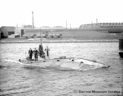
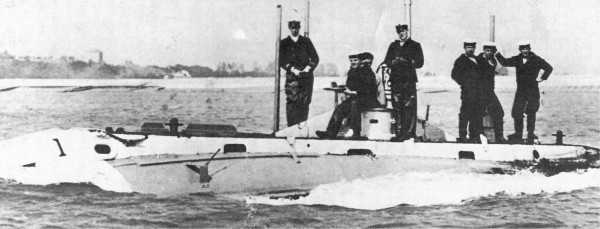
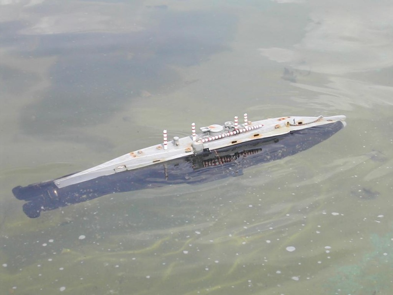
I like to build British submarines built in (or close to) Barrow in Furness. (The modeling world has enough U boats!) So my little fleet of an R Class and Resurgam 2 and a Holland all fit the bill.
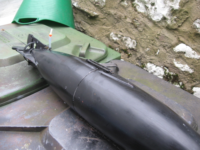
Holland 1 is especially important since she was built in Barrow (under great secrecy) and was the RN’s first submarine. Some of you may remind us that she was built to an American design of the Irish/American genius John Holland. Well yes, but she is quite different in deck shape to the US ones and our own very resourceful Captain Bacon added lots of extra features such as the periscope. His early periscope used to invert the image when you looked astern!
What is also nice is that the Hollands (all 5 of them) didn’t kill anyone of any side. The ultimate deterrent.
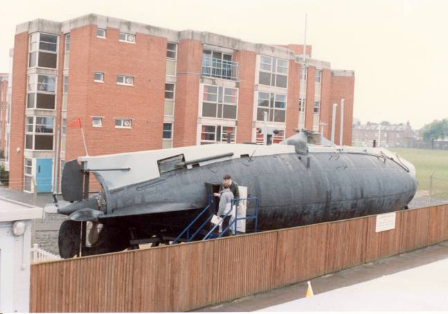
Holland 1 herself sank off the Eddystone on the way to the breakers in 1913 but was recovered in 1981 and can be seen today at the RN Submarine museum, Gosport. I have many photos and the museum staffs were immensely helpful.
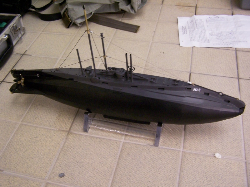
For the model, I was very impressed by Nigel Edmond’s Holland 2 (Which has now sadly been sold on several times and has ended up gathering dust in a less than good home!) Nigel had made the fiberglass version from a fragile ply model which had been provided by Fred Ellis. Steve Webb had started work on one of Nigel’s mouldings before his death and I would like to thank Dianne Webb for agreeing to sell the unfinished model.
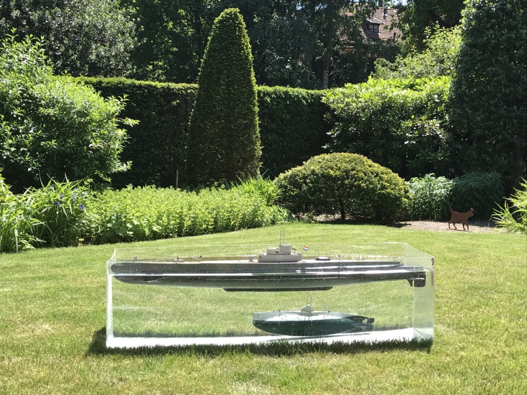
Nigel's model:
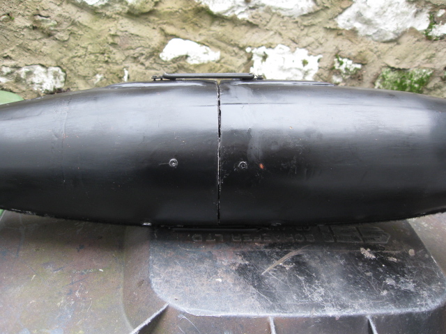
Steve had started work on an aluminium bayonet type hull closure which used a vertical split about 1/3 of the way up from the stern.
Nigel used a similar arrangement with a buoyancy bag system and he also strongly recommended the use of a sliding weight trim system using the batteries.
However I prefer the pumped pressure tank system and I intended to use Lipo batteries for the first time which are a bit light to use as a moving weight.
So some initial sketches (By the shores of Lake Como as it happened until Avril reminded me we were on holiday!) suggested that:
The pressure tank should be circular and a lead trim weight could be “wrapped round” it and operated by a mini servo.
The pressure tank “wastes” about ½ to 1/3 of the tank volume because of the compressed air bubble and so fitting everything into to such a small and elongated egg shape would be very difficult.
The use of a WTC would waste too much space.
On returning home, I filled the 2 hull sections up with water and found that displacement was about 3.75 liters.
I estimated that the ballast tank volume should be about 10% of this which gave a water fill of 375 ml.
A 140 mm length of 68mm diameter PVC gutter pipe fitted well in the hull (Have I said how much I like PVC pipe!) I made the ballast tank by making 2 PVC end caps for the tube and fitted a single brass pipe for water inlet and outlet. The tank was glued together and leak tested and then coated with 3 layers of glass matt and resin to allow it to stand the pressure.
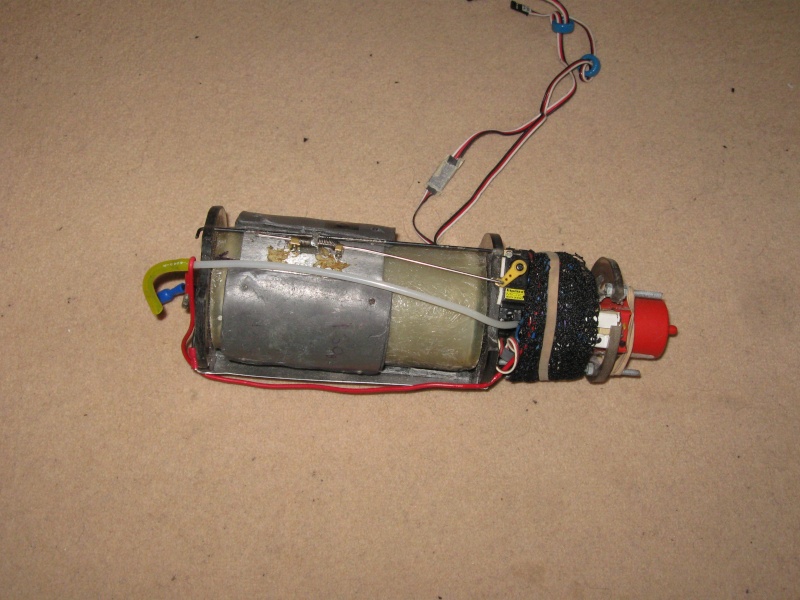
That was OK so far but the next thing was the bayonet sealing ring and sealing the shafts for the control surfaces (No WTC possible.) The shaft seals were sorted quickly – O rings inside a brass tube glassed into the hull – reliable on a test setup.
The bayonet rings were trickier. The ones that Steve had made were designed for the hull cut near the stern and were quite sturdy. The net result was that fitting things in to the hull was like getting a ship in a bottle, if you see what I mean. So it had to be a hull division in the centre at the widest point.
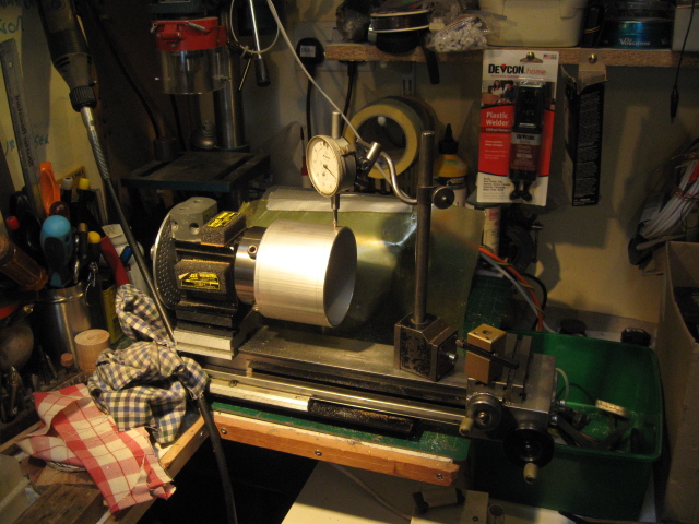
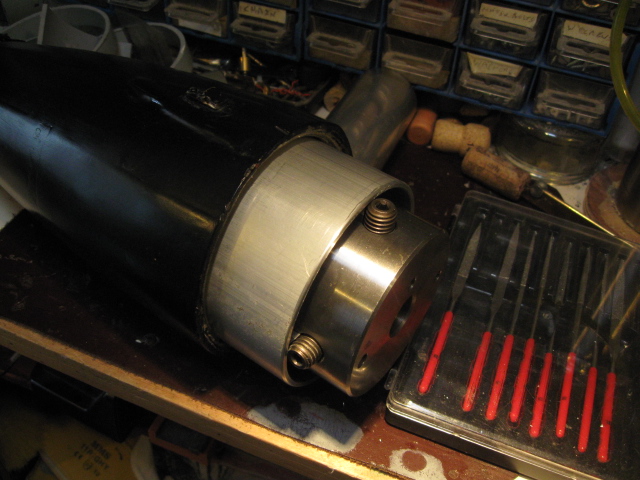
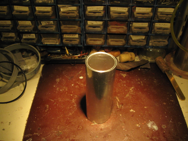
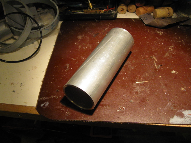
Back to PVC sewer pipe – and an experiment. Take a piece of 110mm pipe and cut lengthwise slices a few mm wide lengthwise until it can just be pushed into a piece of 4” pipe. When it does, glue the cut together with PVC cement and then glue this into a piece of 4” pipe.
Fix this on a lathe faceplate (Not very easy because it is quite flexible.) Take a skim cut. Cut a groove around this piece. Insert a 2mm cross section O ring . Grease it and push into other piece of sewer pipe. Leak test. It seals again and again! Result a slim line bayonet fitting which costs about 20p!
The next problem was that the hull needed to be cut in the centre and my new bayonet ring diameter is a little bit big to fit in the existing hull. The simplest thing to do was to actually make a new hull cast from the old one.
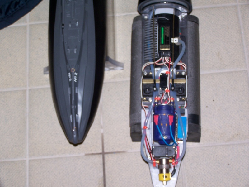
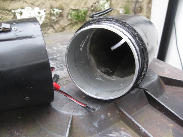
So I made a female mould and then made 2 male moulds. I glassed them together with 2 pieces of PVC pipe inserted (See photo) The smaller diameter piece was to make it easier to insert PVC bow and end caps. The PVC pipes were covered with pva release agent.
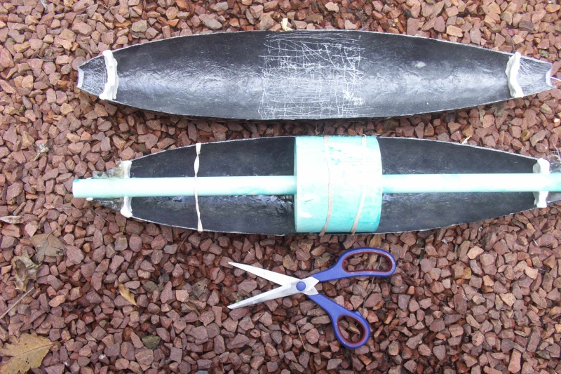
Once everything had cured, I cut the whole thing in half and glassed the inside hull seams. I then removed all the pieces of PVC pipe.
I then started to fit the hull out. The bow was easy – a solid PVC plug with a hole for a nylon pipe to allow water to be pumped in and out of the ballast tank. The torpedo tube hatch would eventually cover this.
I fixed my PVC bayonet fitting into the centre section with silicone rubber.
The stern cap was drilled for a 4mm stainless steel prop shaft. The shaft was sealed with a Simrit seal with a ball race on the dry side.
The drive motor was a multi-pole Buhler motor from Model Motors Direct with a 3 to 1 gear reduction (Graupner gears.)
My attention then turned to the sliding weight system which Nigel had recommended.
There is a useful formula in Norbert Bruggen’s book which enables you to calculate the effect of this. This showed that a “wrap around” weight on the ballast tank would give a useful pitch change from a typical servo throw. (See photo) The weight slides on PTFE blocks to reduce friction and the photo also shows the spring system to avoid servo damage if you hit something.
The next thing was to fit everything in – difficult with much trial and error!
One extra complication was that the Pinger had to work from inside the submarine. There was no free flooding area on this submarine. I bonded a piezo ceramic transducer to the inside hull at the stern and this was plugged into a modified Pinger.
The assembly for the rudder and hydroplanes was a little tricky to visualize from the drawings and I made it up from sheet PVC. The rudder and planes were made from polycarbonate.
The prop was also a problem because there is nothing like it available commercially – it is a large disk with small blades. I knew this was going to be a trial and error job. So I mocked one up from an aluminium disk with slits cut in it and stuck some twisted pieces of aluminium in with Evostik. It lasted long enough to tell me whether it would work or not!
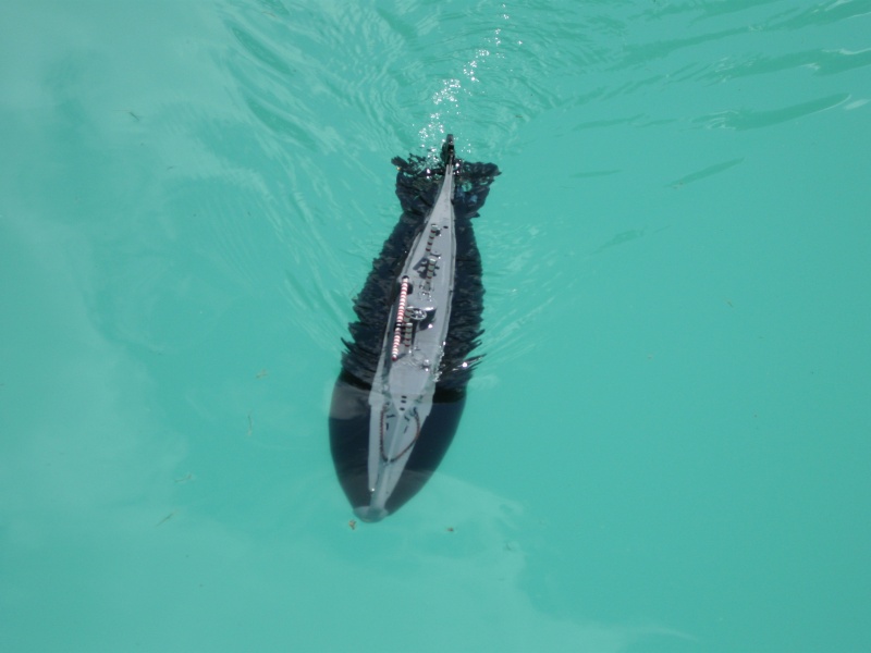
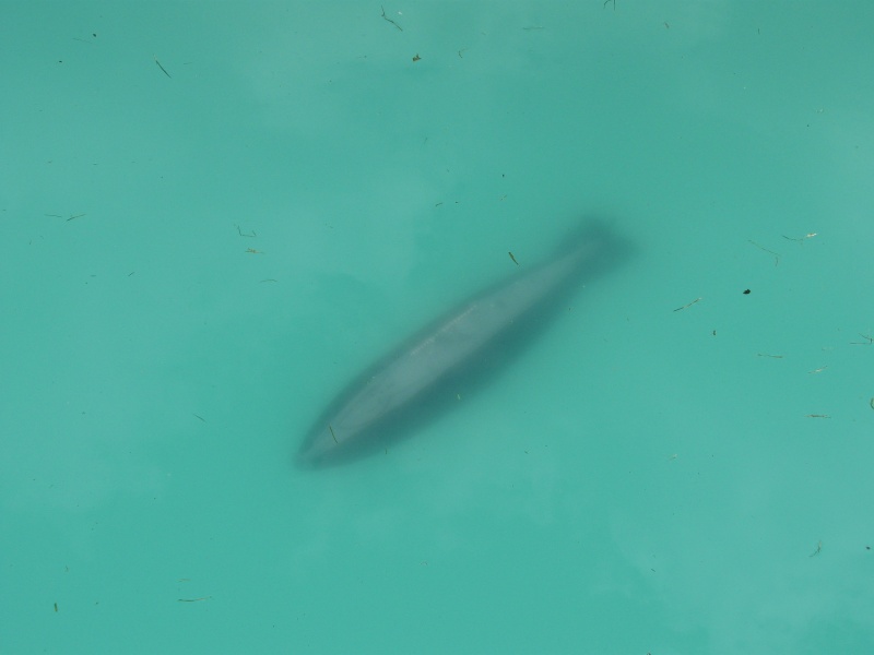
Initial ballasting was done in the bath and it was found that the sliding weight system worked very nicely. You can make the Holland nod and bow!
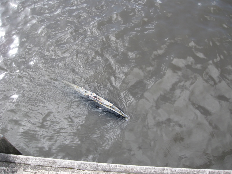
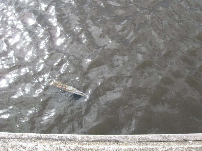
Lots of pond tests at the Barrow in Furness MBC followed. A lot of experiments went into the prop to get a reasonable model speed. The blade area and pitch were increased and the prop was eventually made of brass with brass blades soft soldered.
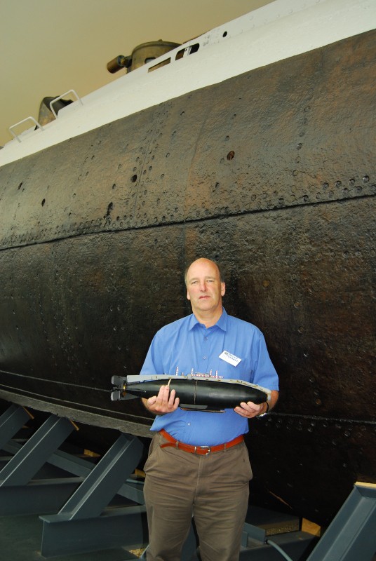
The crowning achievement was the weekend display at the RNSM, Gosport and the photo of the model in front of the real one.
She is a very nice little sub to maintain and operate and always attracts interest at the pond side.
Oh and the original hull is still available (and it includes the superstructure moulding) to a "good" home i.e an AMS member who will actually build something and donate £50 to the AMS.
Next installment next Saturday.
David
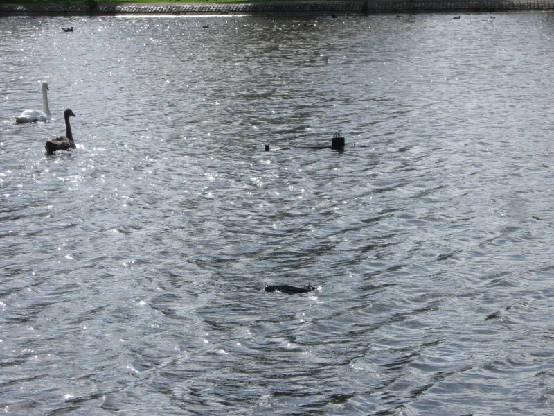
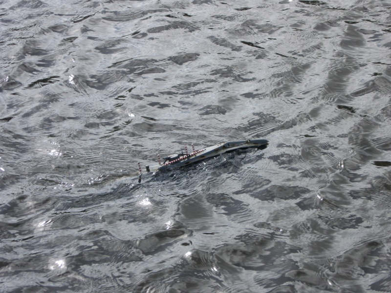
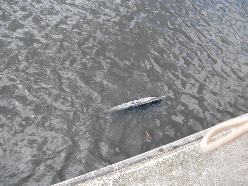
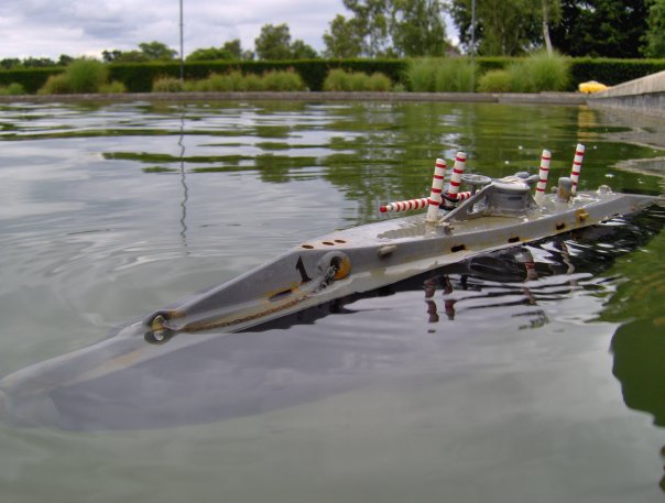
 [/quote]
This article was written in June 2011 and published in the AMS magazine shortly afterwards. I have recently been doing a little bit of refurbishment, and so it seemed like a good moment to start this thread.
The original article follows and I will publish the update next Saturday:


I like to build British submarines built in (or close to) Barrow in Furness. (The modeling world has enough U boats!) So my little fleet of an R Class and Resurgam 2 and a Holland all fit the bill.
Holland 1 is especially important since she was built in Barrow (under great secrecy) and was the RN’s first submarine. Some of you may remind us that she was built to an American design of the Irish/American genius John Holland. Well yes, but she is quite different in deck shape to the US ones and our own very resourceful Captain Bacon added lots of extra features such as the periscope. His early periscope used to invert the image when you looked astern!
What is also nice is that the Hollands (all 5 of them) didn’t kill anyone of any side. The ultimate deterrent.
Holland 1 herself sank off the Eddystone on the way to the breakers in 1913 but was recovered in 1981 and can be seen today at the RN Submarine museum, Gosport. I have many photos and the museum staffs were immensely helpful.
For the model, I was very impressed by Nigel Edmond’s Holland 2 (Which has now sadly been sold on several times and has ended up gathering dust in a less than good home!) Nigel had made the fiberglass version from a fragile ply model which had been provided by Fred Ellis. Steve Webb had started work on one of Nigel’s mouldings before his death and I would like to thank Dianne Webb for agreeing to sell the unfinished model.
Nigel's model:


Steve had started work on an aluminium bayonet type hull closure which used a vertical split about 1/3 of the way up from the stern.
Nigel used a similar arrangement with a buoyancy bag system and he also strongly recommended the use of a sliding weight trim system using the batteries.
However I prefer the pumped pressure tank system and I intended to use Lipo batteries for the first time which are a bit light to use as a moving weight.
So some initial sketches (By the shores of Lake Como as it happened until Avril reminded me we were on holiday!) suggested that:
The pressure tank should be circular and a lead trim weight could be “wrapped round” it and operated by a mini servo.
The pressure tank “wastes” about ½ to 1/3 of the tank volume because of the compressed air bubble and so fitting everything into to such a small and elongated egg shape would be very difficult.
The use of a WTC would waste too much space.
On returning home, I filled the 2 hull sections up with water and found that displacement was about 3.75 liters.
I estimated that the ballast tank volume should be about 10% of this which gave a water fill of 375 ml.
A 140 mm length of 68mm diameter PVC gutter pipe fitted well in the hull (Have I said how much I like PVC pipe!) I made the ballast tank by making 2 PVC end caps for the tube and fitted a single brass pipe for water inlet and outlet. The tank was glued together and leak tested and then coated with 3 layers of glass matt and resin to allow it to stand the pressure.

That was OK so far but the next thing was the bayonet sealing ring and sealing the shafts for the control surfaces (No WTC possible.) The shaft seals were sorted quickly – O rings inside a brass tube glassed into the hull – reliable on a test setup.
The bayonet rings were trickier. The ones that Steve had made were designed for the hull cut near the stern and were quite sturdy. The net result was that fitting things in to the hull was like getting a ship in a bottle, if you see what I mean. So it had to be a hull division in the centre at the widest point.
Back to PVC sewer pipe – and an experiment. Take a piece of 110mm pipe and cut lengthwise slices a few mm wide lengthwise until it can just be pushed into a piece of 4” pipe. When it does, glue the cut together with PVC cement and then glue this into a piece of 4” pipe.
Fix this on a lathe faceplate (Not very easy because it is quite flexible.) Take a skim cut. Cut a groove around this piece. Insert a 2mm cross section O ring . Grease it and push into other piece of sewer pipe. Leak test. It seals again and again! Result a slim line bayonet fitting which costs about 20p!
The next problem was that the hull needed to be cut in the centre and my new bayonet ring diameter is a little bit big to fit in the existing hull. The simplest thing to do was to actually make a new hull cast from the old one.
So I made a female mould and then made 2 male moulds. I glassed them together with 2 pieces of PVC pipe inserted (See photo) The smaller diameter piece was to make it easier to insert PVC bow and end caps. The PVC pipes were covered with pva release agent.

Once everything had cured, I cut the whole thing in half and glassed the inside hull seams. I then removed all the pieces of PVC pipe.
I then started to fit the hull out. The bow was easy – a solid PVC plug with a hole for a nylon pipe to allow water to be pumped in and out of the ballast tank. The torpedo tube hatch would eventually cover this.
I fixed my PVC bayonet fitting into the centre section with silicone rubber.
The stern cap was drilled for a 4mm stainless steel prop shaft. The shaft was sealed with a Simrit seal with a ball race on the dry side.
The drive motor was a multi-pole Buhler motor from Model Motors Direct with a 3 to 1 gear reduction (Graupner gears.)
My attention then turned to the sliding weight system which Nigel had recommended.
There is a useful formula in Norbert Bruggen’s book which enables you to calculate the effect of this. This showed that a “wrap around” weight on the ballast tank would give a useful pitch change from a typical servo throw. (See photo) The weight slides on PTFE blocks to reduce friction and the photo also shows the spring system to avoid servo damage if you hit something.
The next thing was to fit everything in – difficult with much trial and error!
One extra complication was that the Pinger had to work from inside the submarine. There was no free flooding area on this submarine. I bonded a piezo ceramic transducer to the inside hull at the stern and this was plugged into a modified Pinger.
The assembly for the rudder and hydroplanes was a little tricky to visualize from the drawings and I made it up from sheet PVC. The rudder and planes were made from polycarbonate.
The prop was also a problem because there is nothing like it available commercially – it is a large disk with small blades. I knew this was going to be a trial and error job. So I mocked one up from an aluminium disk with slits cut in it and stuck some twisted pieces of aluminium in with Evostik. It lasted long enough to tell me whether it would work or not!
Initial ballasting was done in the bath and it was found that the sliding weight system worked very nicely. You can make the Holland nod and bow!
Lots of pond tests at the Barrow in Furness MBC followed. A lot of experiments went into the prop to get a reasonable model speed. The blade area and pitch were increased and the prop was eventually made of brass with brass blades soft soldered.
The crowning achievement was the weekend display at the RNSM, Gosport and the photo of the model in front of the real one.
She is a very nice little sub to maintain and operate and always attracts interest at the pond side.
Oh and the original hull is still available (and it includes the superstructure moulding) to a "good" home i.e an AMS member who will actually build something and donate £50 to the AMS.
Next installment next Saturday.
David


 [/quote]
Last edited by david f on Mon Mar 02, 2015 11:44 am; edited 2 times in total






» WW2 mini sub build
» sonar data link
» Robbe Seawolf V2
» ExpressLRS - 868/915 Mhz equipment
» Flight controllers as sub levelers
» 868/915 Mhz as a viable frequency for submarines.
» Futaba -868/915mhz equipment
» Microgyro pitch controller corrosion