Ok guy’s I’ have done some more work on my tooling.
As previous stated I have three tools for the sub, all three are finished now, the finish is not what I wanted to be but I’m forced to be left handed for the moment.
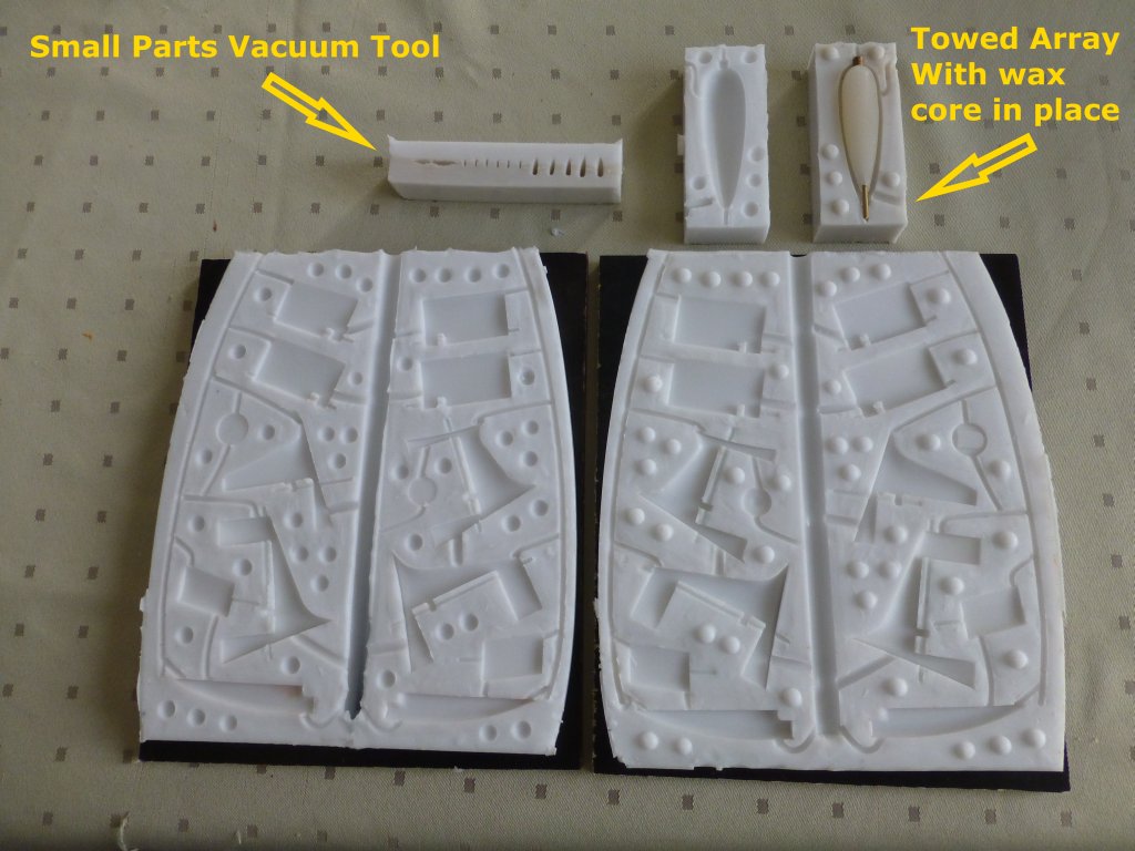
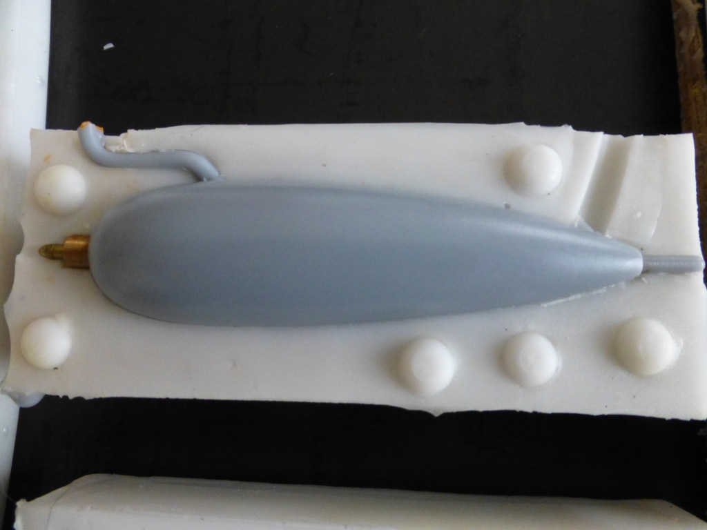
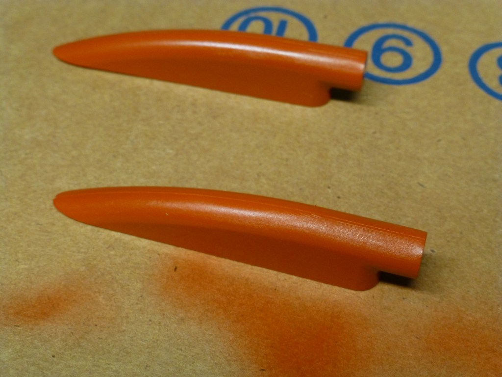
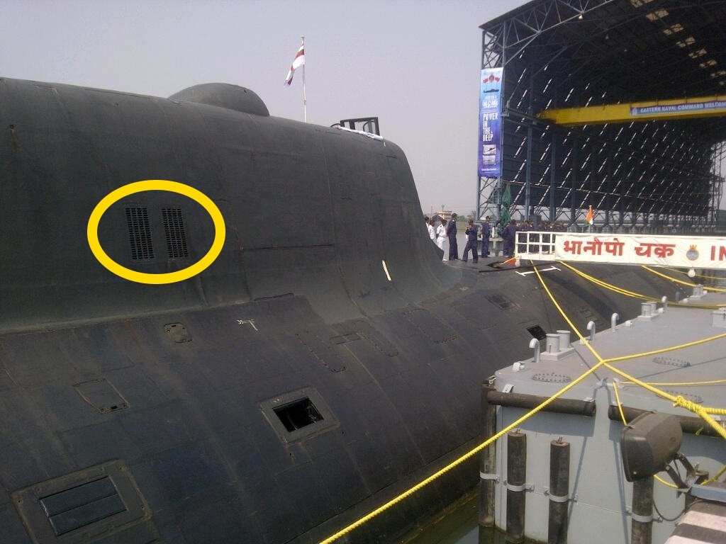
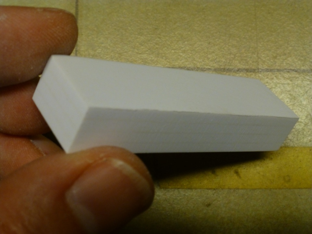
N°1: The towed array pod tool is a straight forward the wax is in place
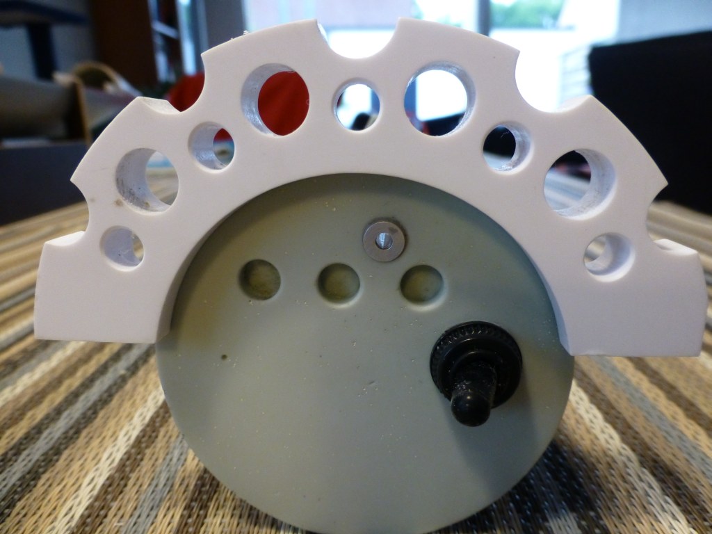
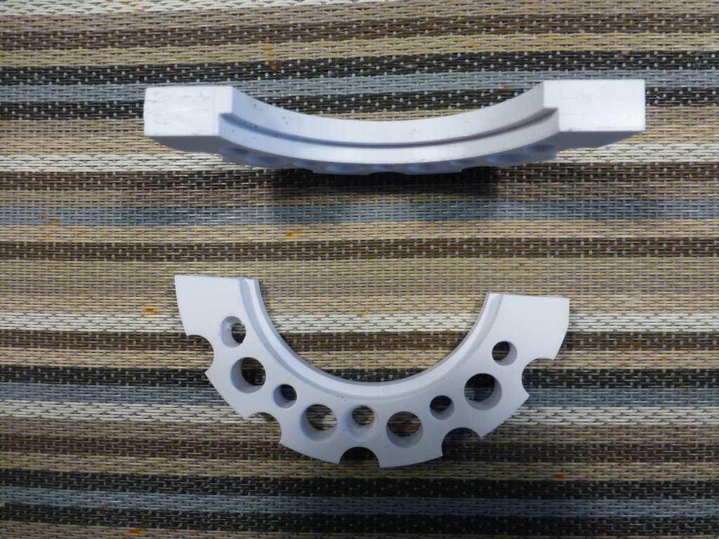
N°2: The small parts tools for vacuum casting, this tool is a little special as it’s is a pocked tool what I mean with that is that three of outer edges of one of the tool halves was not sprayed with release agent and consequently both halves are permanent fixed together at those places. The tool only can open were the castings are positioned in order to get them out.
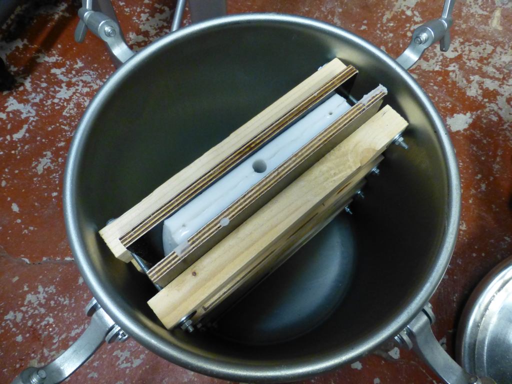
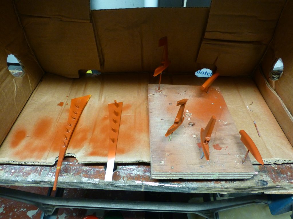
N°3: The third one is the largest tool I made so far. I have dimensioned it so it will just fit my pressure pot. I had some trouble to get both halves of the tool leak free when I squeezed them together. (YES I ALWAYS TEST MY TOOLING USING WATER AND YES I’M CRAZY BUT SPILS ARE EXPENSIVE). I normally used David’s way by applying rubber bands bud it failed I could not reach enough pressure to prevent water pouring out in some areas.
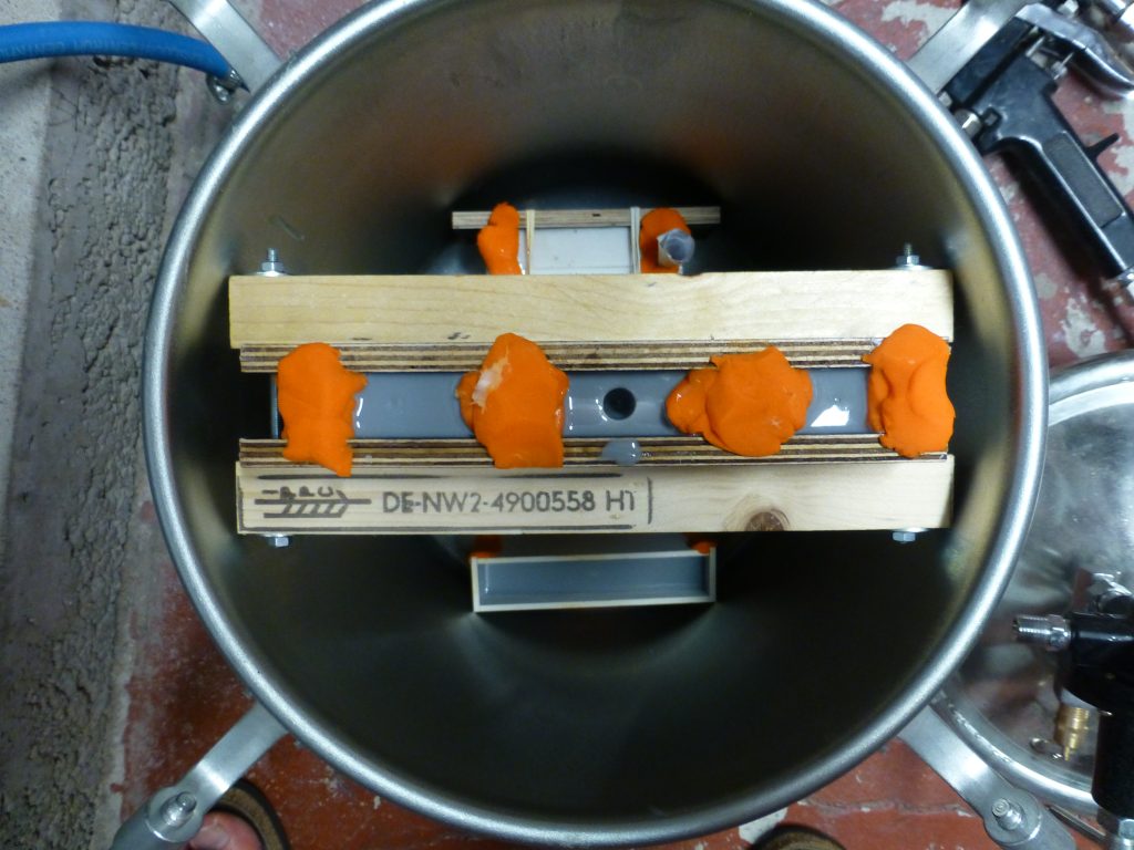
As space is very limited in the pressure pot I fabricated some clamps that, when in place, just fitted in the pressure pot. The clamps made out of some wood leftovers and 4mm threaded studs. The test was OK now no more leaks.


Today I have done the casting
.....no leakages........
the vacuum casting worked well David Merriman, MANY thks for your explanation on that. After degassing the tool I placed it in the pressure pot together with the rest of the tools.
I have to wait some days to see the result (it takes 7 days to fully harden). Hope the prep work pays off.
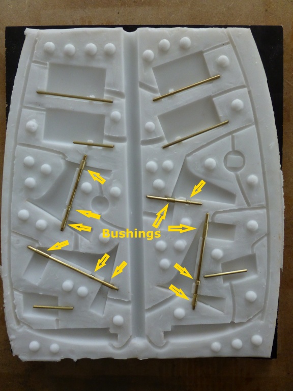
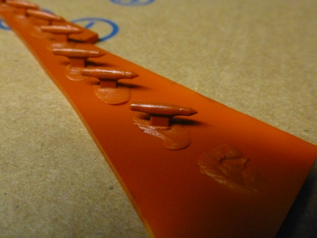
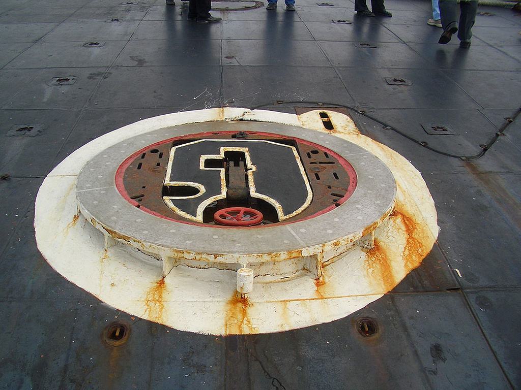
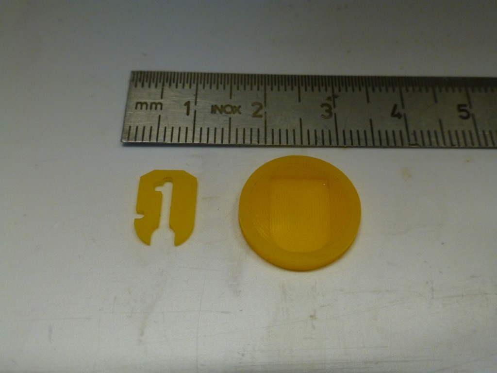
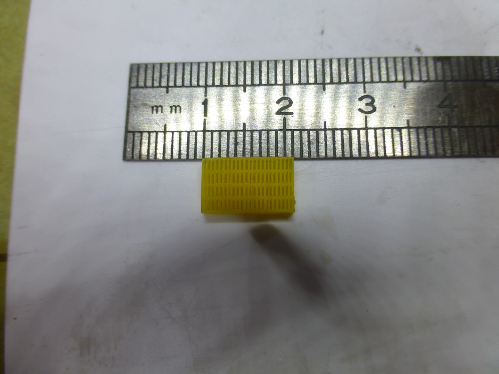
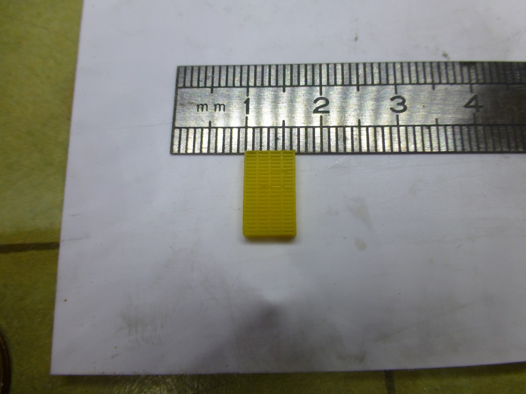
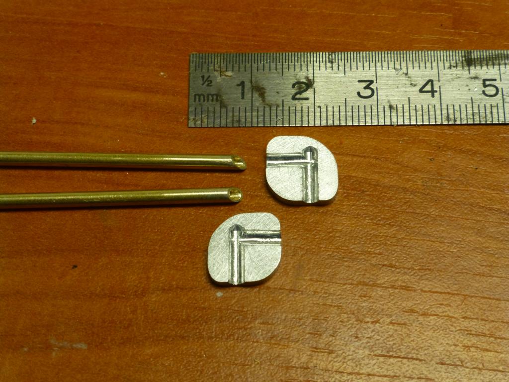
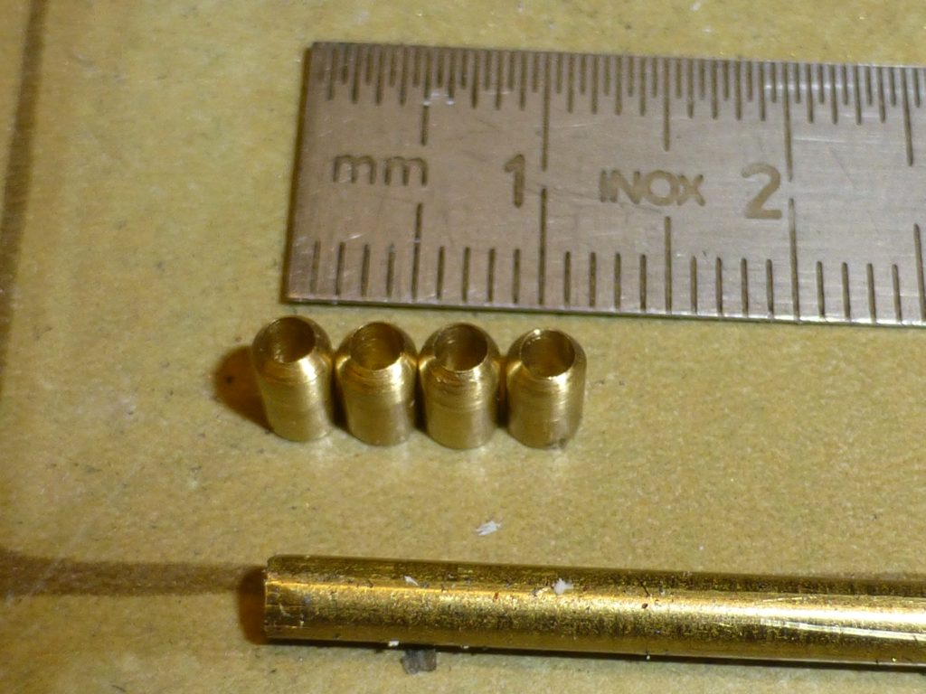
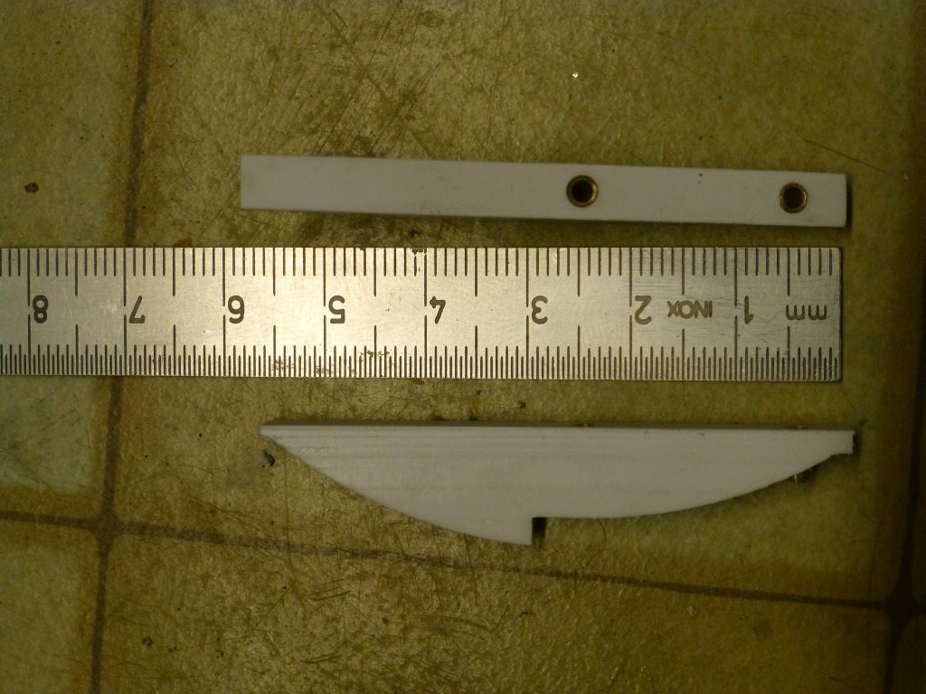
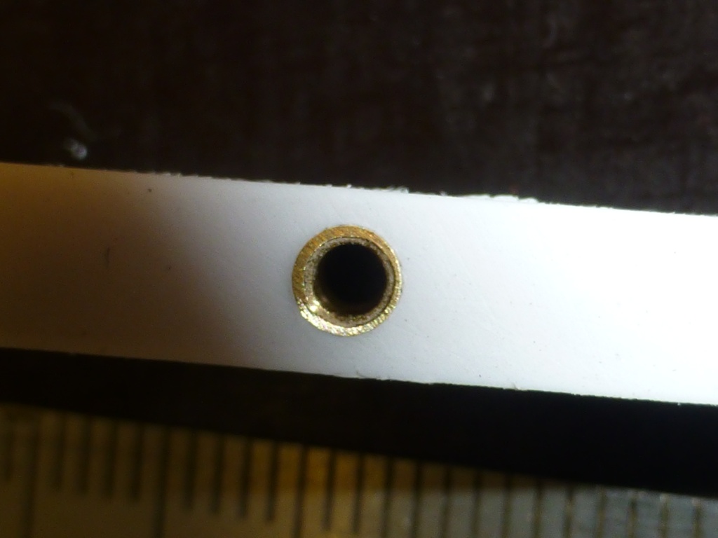
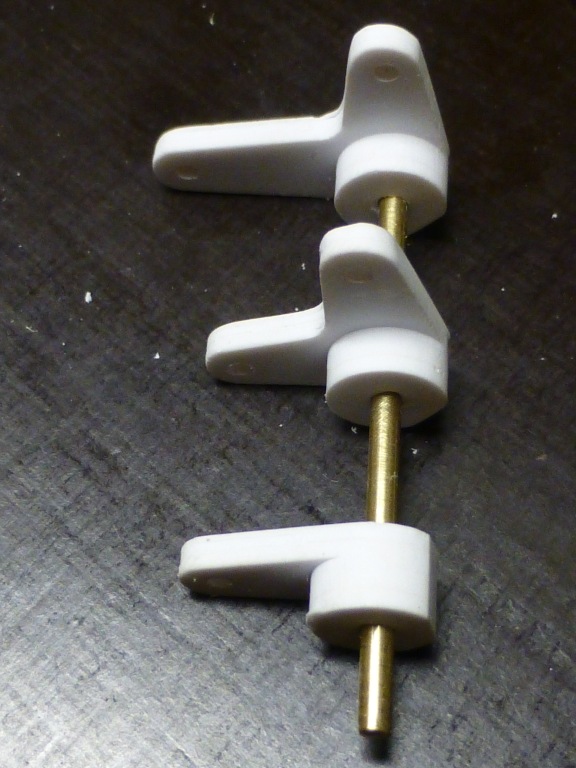
The picture is showing the cores in place together with the bushings witch will be embedded in the parts.
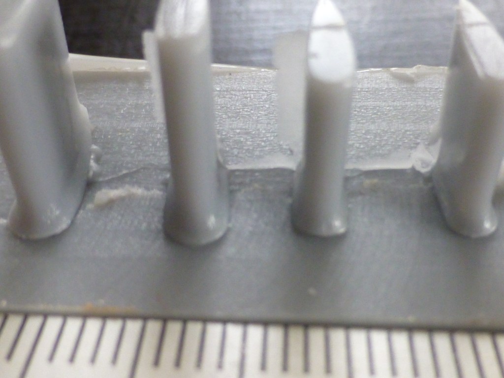
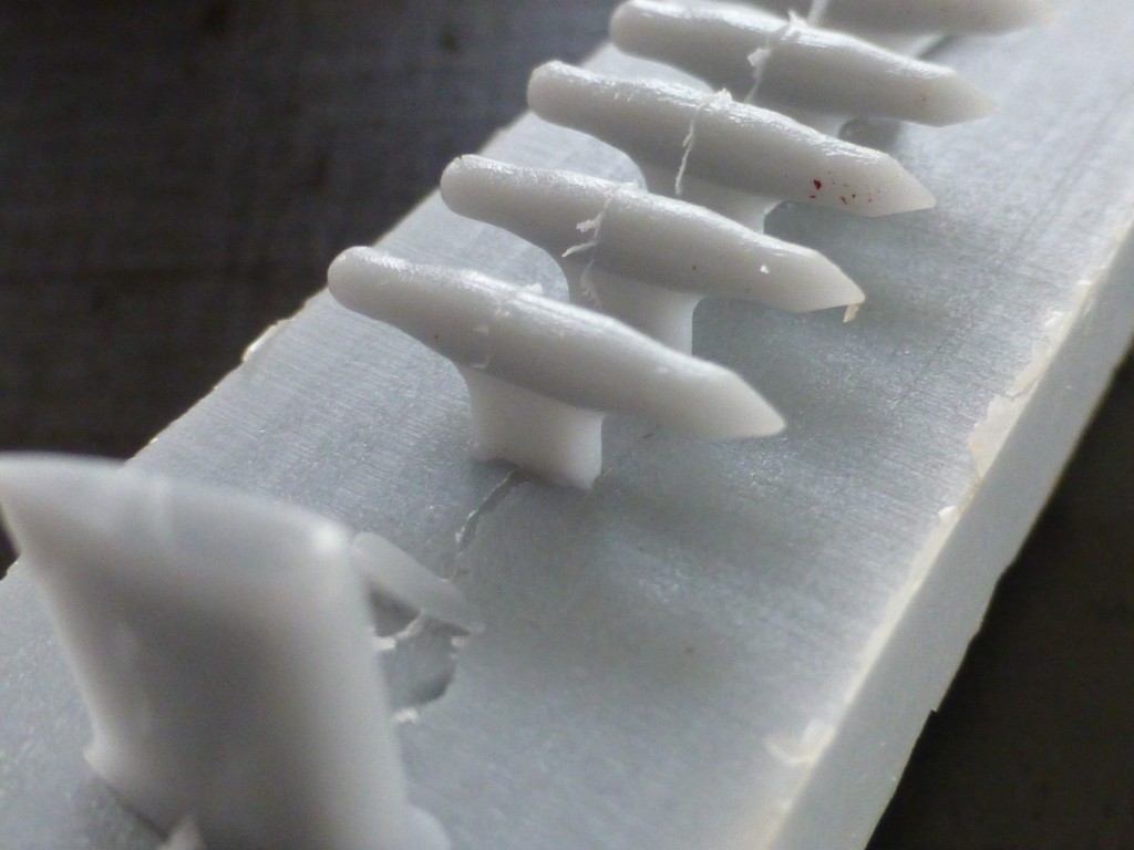
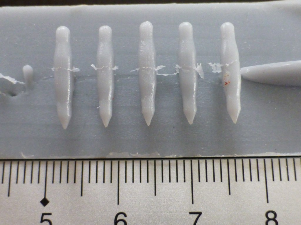
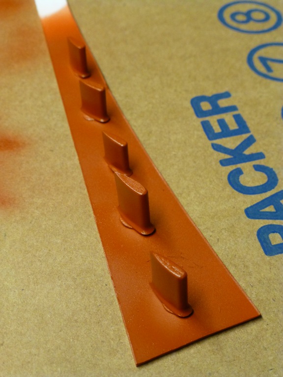
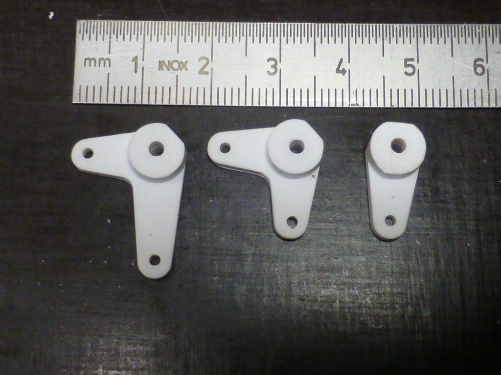
Today after 6 days of curing I could open the pressure pot and see the result.
I was very happy everything worked out very well.....It's all in the prep gents.
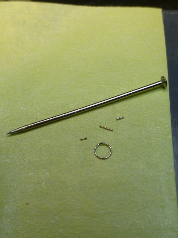
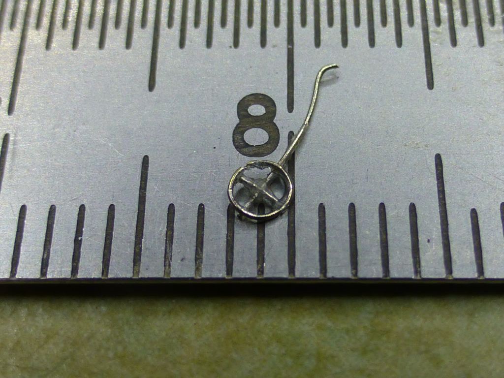
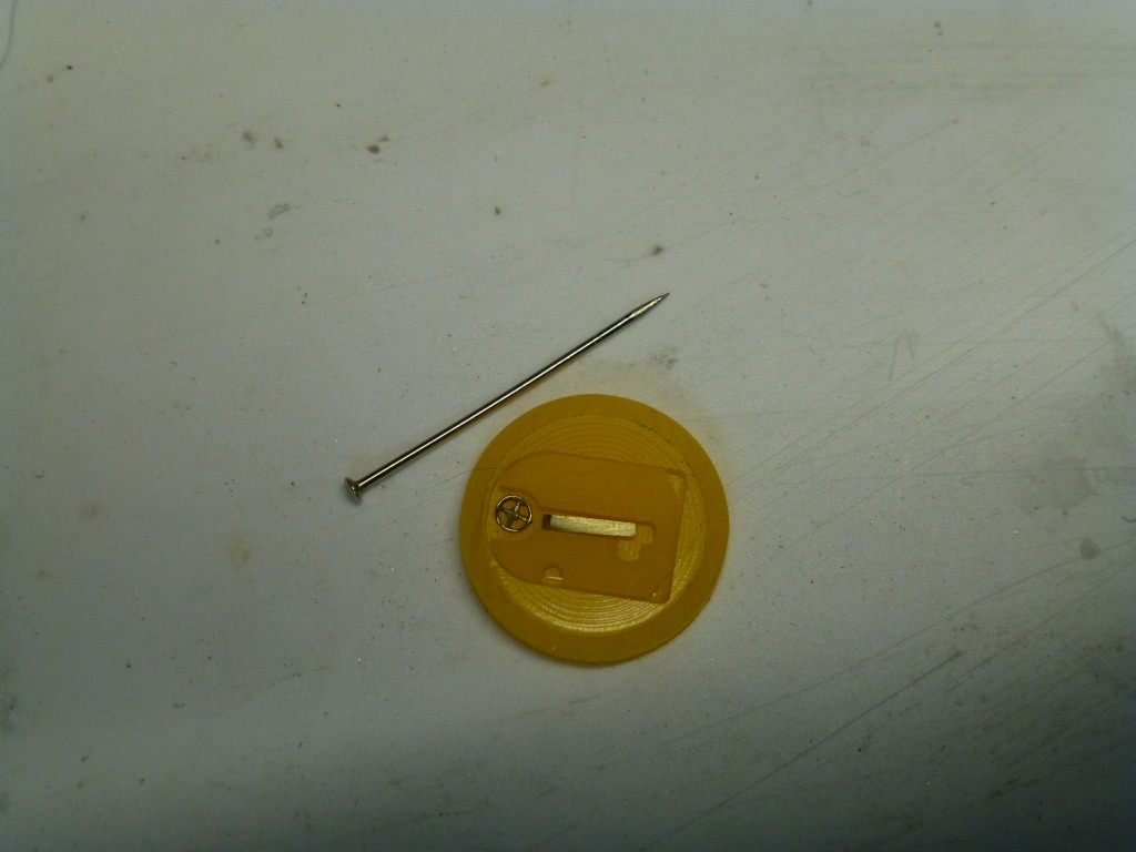
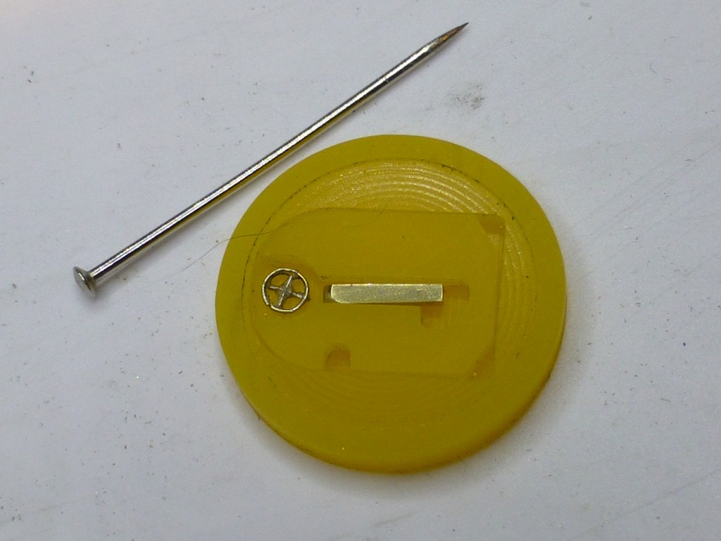
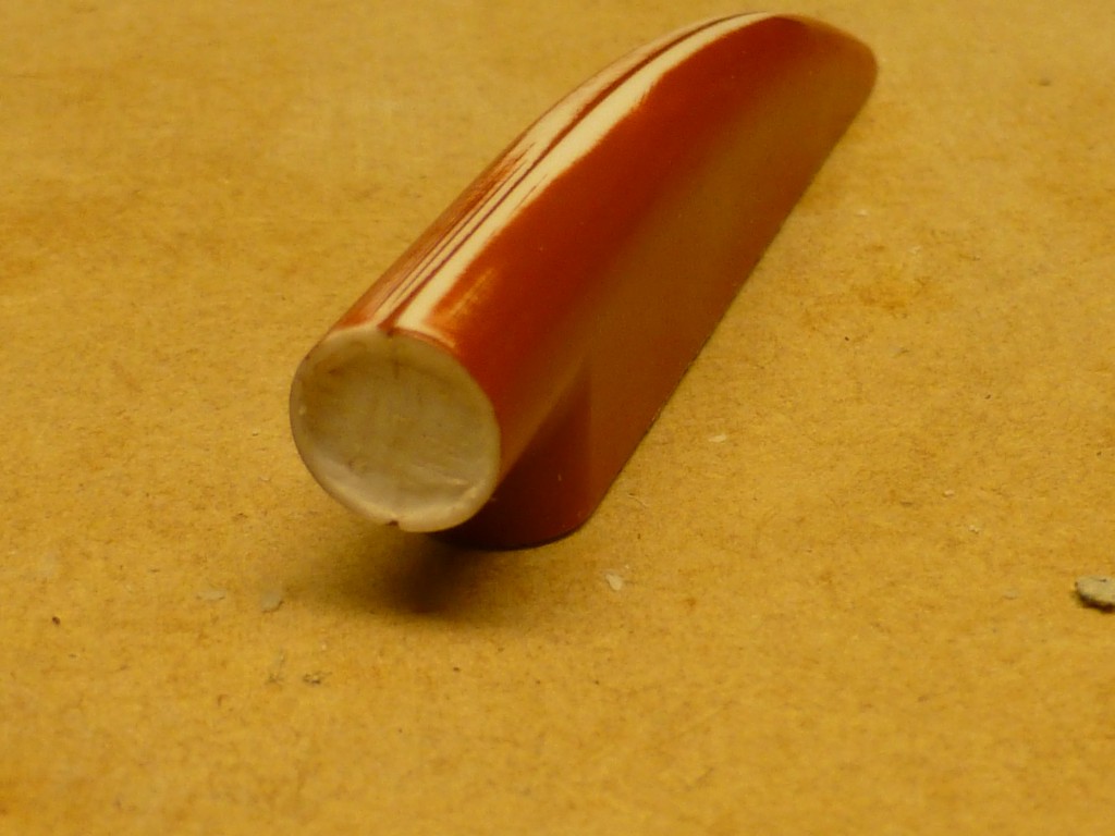
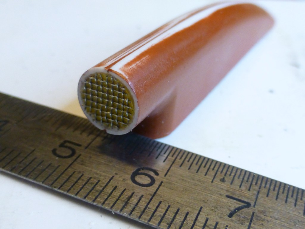
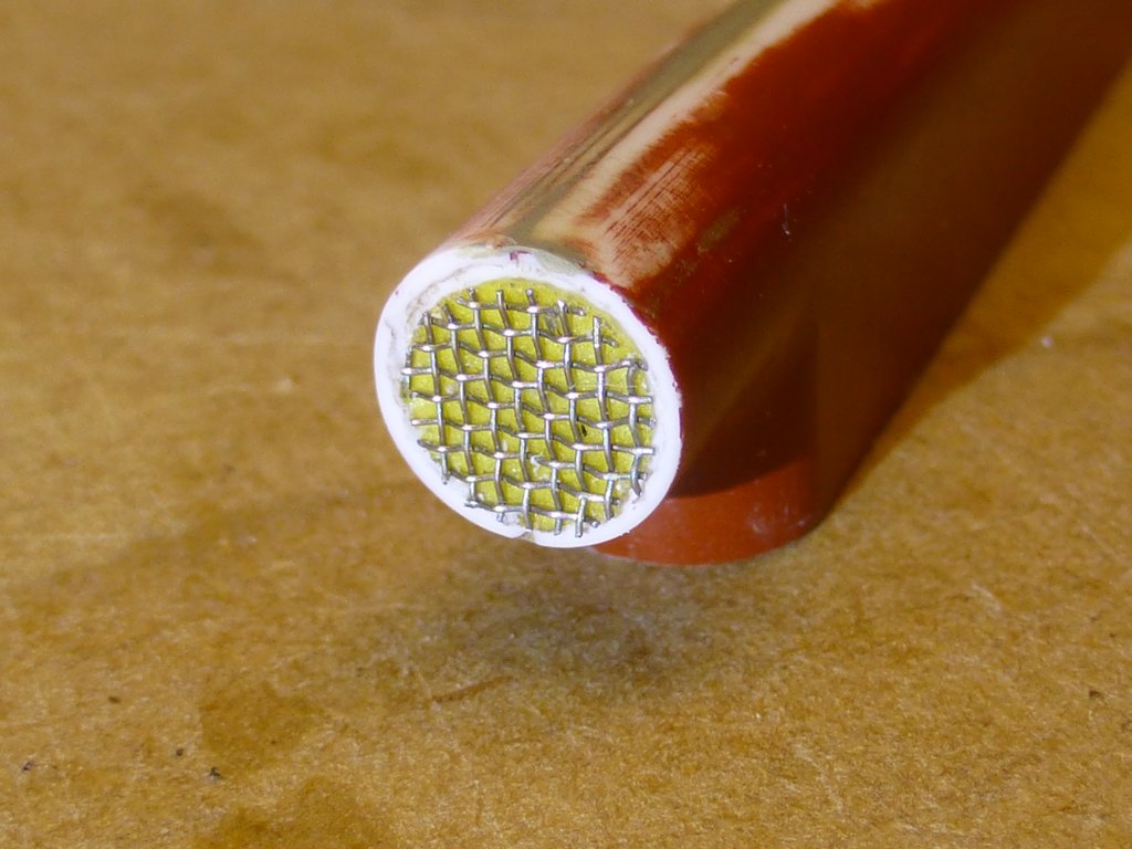
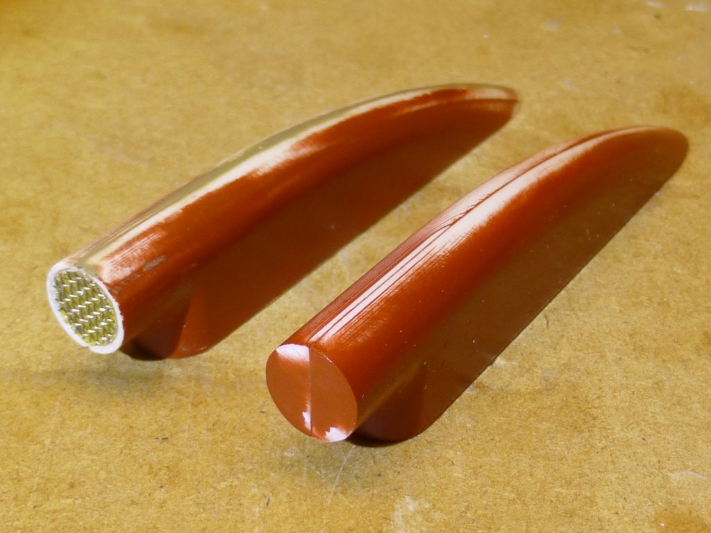
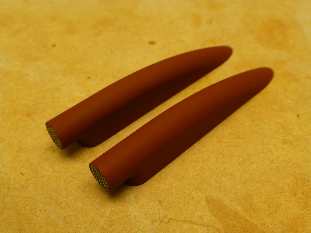
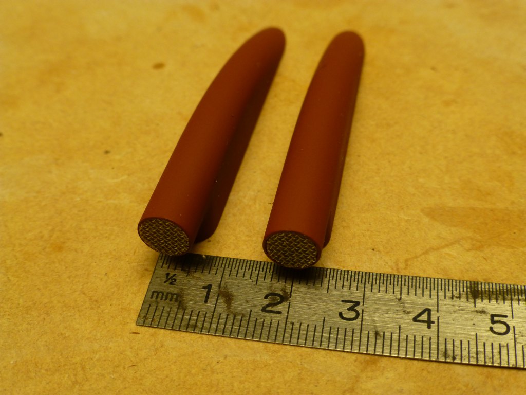
The overkill bushings were encapsulated perfectly and the vacuum casted tiny pieces are incredible, no air bubble what so ever.
Lets not forget that I could not have accomplished this result without the help/guidance/instructions of David Merriman.
Grtz,
Bart


» Modulated electric fields for submarine communication in a "heads up" from Harry!
» Laser cut Robbe U47 conversion
» ExpressLRS - 868/915 Mhz equipment
» Information on camouflage patterns for German seahund
» WW2 mini sub build
» Not the hobby I expected :)
» Sheerline gasket material
» Choice of CAD software and Printer for 3D printing